
Service manual


DV-L70S
DV-L70BL
DV-L70W
10
1. DAC adjustment
(1) TV1 adjustment
Adjustment VR GAM0
Initial value "44" adjustment is unnecessary.
Adjustment VR SBRI
Adjustment Point ————
Input Signal/Setting It is set in "56".
Adjustment VR GPOS
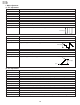
Adjustment Point Connect the oscilloscope to COM output (6PIN of TP1901) and GND.
Input Signal/Setting Black-and-white 10STEP
Adjustment Method Adjust the common amplitude to 8.0±0.1Vp-p.
8.0±0.1Vp-p
Adjustment VR WB-R
Adjustment Point Connect the oscilloscope to 3PIN (VG) and 4PIN (VR) of TP1901.
Input Signal/Setting Black-and-white 10STEP
Adjustment Method Adjust the white balance (red) so that peak-peak the equal of green and red output become equal.
(2) TV2 adjustment
Adjustment VR WB-B
Adjustment Point Dual the oscilloscope to 3PIN (VG) and 5PIN (VB) and GND of TP1901.
Input Signal/Setting Black-and-white 10STEP
Adjustment Method Adjust the white balance (blue) so that peak-peak the equal of green and blue output become equal.
Adjustment VR SCOL
Adjustment Point Connect the oscilloscope to 5PIN (VB) and GND of TP1901.
Input Signal/Setting 100% color bar
Adjustment Method Adjust the blue amplitude of the color bar (black level to peak level) to 3.8±0.1Vpp.
Adjustment VR GAM2
Adjustment Point Connect the oscilloscope to 3PIN (VG) and GND of TP1901.
Input Signal/Setting Black-and-white 10STEP
Adjustment Method Adjust the Vpp of VG to 4.3±0.1Vp-p.
4.3±0.1Vp-p
Adjustment VR CONT
Adjustment Point Connect the oscilloscope to 3PIN (VG) and GND of TP1901.
Input Signal/Setting Black-and-white 10STEP
Adjustment Method Adjust the Vpp of VG to 3.3Vp-p.
3.3±0.1Vp-p
White level
Black level
Sync.