
Service manual


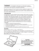


DV-L70U
Parts Code Price Code Remarks Parts Code Price Code Remarks
QCNW-8145GEZZ AQ P.U. extension, 30-pin QCNW-8151GEZZ AQ Inverter extension, 6-pin
QCNW-8146GEZZ AQ Spindle extension, 13-pin QCNW-8152GEZZ AQ LCD panel extension, 32-pin
QCNW-8147GEZZ AN Sled extension, 2-pin QCNW-8154GEZZ AQ Operation PWB extension, 12-pin
QCNW-8148GEZZ AM Power supply extension, 14-pin QCNW-1766TAZZ BF Inverter junction PWB
QCNW-8149GEZZ AQ Main LCD extension, 14-pin QPWBF5002GEZZ BF LCD junction PWB
QCNW-8150GEZZ AQ Main LCD extension, 14-pin QPWBF5003GEZZ BF Pickup junction PWB
Adjustment VR R1102
Adjustment Point Put a voltmeter between 6PIN (+7.5V) and 4PIN (GND) of TP1191.
Input Signal/Setting No input
Adjustment Method Adjust it to 7.50±0.02V.
Adjustment VR R1103
Adjustment Point Visual observation of the panel
Input Signal/Setting Monoscope full screen
Adjustment Method Adjust the screen so that it is located in the center.
Adjustment VR R1104
Adjustment Point Observe the 3PIN of TP1191 with a frequency counter.
Input Signal/Setting No input, external input mode
Adjustment Method Adjust it so as to get the HSY frequency of 15.735±0.01KHz
(63.554µS).
HSY
15.735KHz
(63.554µS)
6-2. ADJUSTMENT PROCEDURE AND METHOD OF LCD PWB SIDE
1. 7.5V adjustment
2. Free run adjustment
3. Screen center adjustment
6-1
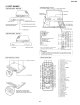
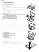
Drawing for service jigs
Operation cabinet
Mechanism
Power
supply PWB
PA
AE
AD
AC
AA
CN302
CN301
AB
MA
FFC
FFC spindle
Lead wire
FFC
Pickup junction PWB
QPWBF5003GEZZ
Pickup
QCNW-8145GEZZ
QCNW-8146GEZZ
QCNW-8147GEZZ
Sled
Power supply, 14-pole
QCNW-8148GEZZ
QCNW-8154GEZZ
QCNW-8150GEZZ
LCD junction
QCNW-8152GEZZ
LCD junction PWB
QPWBF5002GEZZ
Inverter junction PWB
QCNW-1766TAZZ
Inverter
QCNW-8151GEZZ
Inverter PWB
QCNW-8149GEZZ
Lead wire
LC
LB LA
LCD
LCD PWB
F
F
C
F
F
C
Panel
Main PWB
6. ADJUSTMENT METHOD
6-1. HARNESS LIST FOR SERVICE PARTS