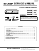
DV-NC70U/C DV-NC72U SERVICE MANUAL S62K3DV-NC70U VCR/DVD COMBINATION MODEL POWER EJECT/STOP / REW PLAY PLAY REC CH AV 2 IN VIDEO L(MONO)-AUDIO-R STOP OPEN/CLOSE TIMER VCR/DVD SELECTOR VCR DVD MODELS DV-NC70U DV-NC70C DV-NC72U In the interests of user-safety (Required by safety regulations in some countries) the set should be restored to its original condition and only parts identical to those specified be used. CONTENTS Page 1. IMPORTANT SERVICE NOTES .......................................
DV-NC70U/C DV-NC72U 1. IMPORTANT SERVICE NOTES etc.) and measure the AC voltage drop across the resistor. Reverse the AC plug on the set and repeat AC voltage measurements for each exposed part. Any reading of 0.45V rms (this corresponds to 0.3mA rms AC.) or more is excessive and indicates a potential shock hazard which must be corrected before returning the VCR/DVD combination model to the owner.
DV-NC70U/C DV-NC72U 1. NOTES DE SERVICE IMPORTANTES pièces métalliques exposées ayant un parcours de retour au châssis (connexions d’antenne, coffret métallique, tétes de vis, boutons et arbres de commande, etc.) et mesurer la chute de tension CA entre la résistance. Inverser la fiche CA (une fiche intermédiaire non polarisée doit être utilisée à seule fin de faire ces vérifications.) sur l’appareil et répéter les mesures de tension CA pour chaque piéce métallique exposée.
DV-NC70U/C DV-NC72U 2. FEATURES Ë Common Features • A DVD, CD player and VCR all in one. • Simultaneous VCR recording and DVD playback. Ë VCR • Hi-Fi Stereo Sound/Double-Azimuth 4-Heads • Built-in MTS (Multi-channel TV Sound) Decoder • 400 Times Rewind Speed to Fast Forward and Rewind.
DV-NC70U/C DV-NC72U Channel Coverage Antenna Input Video Input Video Output Audio Output (0 dB = 0.775 Vrms) Audio Output (0 dB = 0.
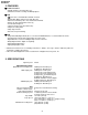
CH REC PLAY REW AV 2 IN VIDEO L(MONO)-AUDIO-R / POWER EJECT/STOP REW PLAY REC CH Tape Speeds Indicator Audio Output Indicator Timer Recording Indicator VCR Mode Indicator Operation status Indicator SEP L R VCR VCR Front Panel Display Front AUDIO/ VIDEO input jack EJECT/STOP POWER VCR Main Unit (Front) VCR DVD TIMER Tape Counter Indicator Channel Indicator Clock Indicator VCR/DVD SELECTOR TIMER indicator PLAY STOP VCR/DVD SELECTOR Cassette compartment OPEN/CLOSE / POWE
PR PB Y COMPONENT R L IN FROM ANTENNA OUT TO TV UHF/VHF CATV VCR ANTENNA OUT OUT TO TV UHF/VHF CATV IN FROM ANTENNA ANTENNA IN (antenna or cable input) VCR AUDIO input jacks DVD/VCR shared AUDIO output jacks VIDEO (MONO) DVD/VCR shared VIDEO output jack VIDEO (MONO) L AUDIO R AUDIO VCR VIDEO L AUDIO R DVD/VCR OUT AV 1 IN DVD AUDIO output jacks VIDEO L AUDIO R DVD/VCR OUT AV 1 IN L AUDIO R DIGITAL AUDIO S-VIDEO DVD OUT VCR VIDEO input jack PR PB Y COMPONENT DV
/ / ) CANCEL / 8 VCR/DVD CHANGE Switch TAPE SPEED CH / STOP REC PLAY REW 100, AM/PM Number buttons CURSOR ( ON SCREEN DISPLAY POWER TAPE SPEED REC REV 100 AM/PM CANCEL RETURN TITLE TV/VCR EJECT DVD SLOW PAUSE/STILL FWD VCR DVD VCR/DVD COMBINATION VCR AUDIO OUTPUT DPSS SKIP STOP PLAY INPUT REPLAY SKIP SEARCH ZERO BACK SET ENTER DVD MENU OPEN/ CLOSE VCR/DVD VCR MENU ON SCREEN SELECTOR DVD SETUP TIMER ON/OFF PROGRAM ANGLE CH FUNCTION CONTROL DISPLAY POWER AUD
DV-NC70U/C DV-NC72U 5. MAINTENANCE CHECK ITEMS AND EXECUTION TIME MECHANICAL PARTS REGUIRING PERIODICAL INSPECTION Use the following table as a guide to maintain the mechanical parts in good operating condition. Parts Pickup Spindle Unit Sled Motor Loading Motor Belt Note Maintained 1,000 hrs. 2,000 hrs. : Part Replacement : Cleaning (For cleaning, use a lint-free cloth danpened with pure isopropyl alcohol.) CARES WHEN USING THE PICKUP 1.
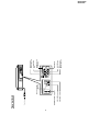
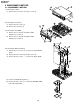
DV-NC70U/C DV-NC72U 6. DISASSEMBLY METHOD 2 1 6-1. DISASSEMBLY METHOD 1) Removing the cabinet. (1) Remove the four screws 1 and one screw 2. 1 2) Removing the front panel. (1) Remove the two screws 3. (2) Release the six hooks 4. 5 4 3 3) Removing the front PWB. (1) Release the one hook 5 and tilt the PWB toward you to remove it. (2) Release the one hook 6 and tilt the PWB toward you to remove it. 4 6 4 4 7 4) Removing the DVD mechanism. (1) Remove the four screws 7 to remove the DVD REINF. angle.
DV-NC70U/C DV-NC72U (6) Remove the two screws e to remove the Power PWB Unit. 5) Removing the Cassette Housing Control/VCR Mechanism. (1) Remove the two screws r. (2) Remove the one screw t. (3) Remove the two screws y. 13 16 14 15 6) Removing the Antenna Terminal Cover/VCR Main PWB Unit. (1) Remove the six screws u. (2) Remove the two screws i. (3) Remove the one screw o. 18 17 19 7) Removing the Bottom Plate. (1) Remove the one screw p.
DV-NC70U/C DV-NC72U 6-2.
DV-NC70U/C DV-NC72U 6-3. REPLACEMENT OF MAIN PARTS 1. Remove the mechanism with angle from the set. (refer to 33 on page 104. Remove K , M , N ) 2. It is in such cases as the thin driver, and it is pushed in slowly, and a tray is drawn in the arrow direction the Slide Rack on the left of the base chassis. 3. Take out disk. Front Side 1.
DV-NC70U/C DV-NC72U 7. OPERATION OF PICKUP 7-1. CIRCUIT CONFIGURATION OF PICKUP The pickup unit reads signals from the disk, and the flexible cable is connected to the board. The following signals flow through the cable. 7-3. POLARITIES OF SIGNAL 7-2.
DV-NC70U/C DV-NC72U 8. ADJUSTMENT, REPLACEMENT AND ASSEMBLY OF MECHANICAL UNITS The explanation given below relates to the on-site general service (field service) but it does not relates to the adjustment and replacement which need high-grade equipment, jigs and skill. For example, the drum assembling, replacement and adjustment service must be performed by the person who have finished the technical courses.
DV-NC70U/C DV-NC72U 8-2 MAINTENANCE CHECK ITEMS AND EXECUTION TIME Perform the maintenance with the regular intervals as follows so as to maintain the quality of machine. Parts Possible symptom encountered Maintained 500 1000 1500 2000 hrs. hrs. hrs. hrs. Abnormal rotation or significant vibration requires replacement. Guide roller ass’y Sup guide shaft Reverse guide Remarks Lateral noises Head occasionally blocked Clean tape contact part with the specified cleaning liquid.
DV-NC70U/C DV-NC72U 8-3. FUNCTION OF MAJOR MECHANICAL PARTS (TOP VIEW) 17 15 18 26 10 16 14 1 9 2 11 3 5 7 8 6 No. 4 12 Function 13 No.
DV-NC70U/C DV-NC72U FUNCTION OF MAJOR MECHANICAL PARTS (BOTTOM VIEW) 21 22 25 19 20 23 No. 24 Function No. Function 19 Syncro Gear 23 Clutch lever 20 Master cam 24 Limiter pulley ass’y 21 Capstan D.D.
DV-NC70U/C DV-NC72U 8-4. DISASSEMBLY AND REASSEMBLY 8-4-1 DISASSEMBLING THE MECHANISM 2. Removing the mechanism and cassette housing. Remove the two screws 2 fixing the cassette housing to the mechanism, and remove the cassette housing. 1. When removing the mechanism from the set. Remove the two screws 1 which connecting mechanism and main frame. Take out vertically the mechanism so that it does not damage the adjacent parts.
DV-NC70U/C DV-NC72U 2. Mechanical initial setting • Rotate the worm gear by pushing the flange manually until return to initial position. • When apply power supply to rotate the loading motor, please remove/unsolder at least one terminal wire. • If voltage applied to loading motor without disconnecting the terminal wire, there is a possibility the capstan motor IC will damage. • The maximum applied voltage is 9V. If more than 9V, there is a possibility the mechanism will damage.
DV-NC70U/C DV-NC72U 8-5 REMOVING AND INSTALLING THE CASSETTE HOUSING • 1. 2. 3. Notes 1. In the case when you use the magnet screw driver, never approach the magnet driver to the A/C head, FE head, and drum. 2. When installing or removing, take care so that the cassette housing control and tool do not contact the guide pin or drum. 3. After installing the cassette housing control once perform cassette loading operation. Removal In the cassette removing mode, remove the cassette. Unplug the power cord.
DV-NC70U/C DV-NC72U Notes: 1. When installing the reel disk, take due care so that the tension band ass'y is not deformed and grease does no adhere. 2. Do not damage the Supply main brake ass'y. Be careful so that grease does not adhere to the brake surface. 8-7 REEL DISK REPLACEMENT AND HEIGHT CHECK • 1. 2. 3. 4. Removal Remove the cassette housing control assembly. Remove the Supply/Take-up main brake ass'y. Remove tension band from the tension arm ass'y. Remove the reel disk.
DV-NC70U/C DV-NC72U Note: Whenever replacing the reel disk, perform the height checking and adjustment. Reel disk height adjusting jig Master plane 10 ± 0.2mm Notes: 1. Hold the torque gauge by hand so that it is not moved. 2. Do not keep the reel disk in lock state. Do not allow longtime measurement. 8-9 CHECKING AND ADJUSTMENT OF TAKEUP TORQUE IN REWIND MODE Mechanism chassis Reel disk A • Remove the cassette housing control assembly.
DV-NC70U/C DV-NC72U Notes: 1. Hold the torque gauge by hand so that it is not moved. 2. Do not keep the reel disk in lock state. Do not allow longtime measurement. 8-11 CHECKING AND ADJUSTMENT OF TAKEUP TORQUE IN VIDEO SEARCH REWIND MODE • Remove the cassette housing control assembly. • After short-circuiting between TP803 and TP802 provided at operation PWB, plug in the power cord.
DV-NC70U/C DV-NC72U 8-12 CHECKING THE VIDEO SEARCH REWIND BACK TENSION • Remove the cassette housing control assembly. • After short-circuiting between TP803 and TP802 provided at main PWB, plug in the power cord. Tension gauge 900 - 1,200gf Pinch roller • Checking 1. After pressing the play button, press the rewind button, and set the video search rewind mode. 2.
DV-NC70U/C DV-NC72U • Checking 1. Set a cassette tape, push the REC button to place the unit in the SP record mode. Now check the tension pole position. 2. Visually check to see if the position of the tension pole is within the 0 +0.5 –0.2 mm from the left side line. CW CC W Tension pole adjustment driver adjusting direction Standard A = 0 + 0.5 mm - 0.2 Tension pole adjustment driver Figure 8-17.
DV-NC70U/C DV-NC72U • Adjustment 1. If the indication of torque cassette meter is lower than the setting, shift the tension spring engagement to the part A. 2. If the indication of torque cassette meter is higher than the setting, shift the tension spring engagement to the part B. A • Checking the brake torque at the take-up side Torque gauge Tension arm B CW CCW Take-up reel disk Tension spring Figure 8-19. CCW: 4.41 ± +2.0 –1.5 mN⋅m (45 ± CW: 4.12 ± +1.5 –1.
DV-NC70U/C DV-NC72U 3. Align the left end of gear of A/C head arm with the punched mark of chassis, tentatively tighten the screws 1 so as to ensure smooth motion of A/C head arm. Tightening torque must be 0.45 ± 0.05N·m (4.5 ± 0.5kgf·cm). 8-17 REPLACEMENT OF A/C (AUDIO/CONTROL) HEAD 1. In eject position unplug the power cord. • Removal 1. Take out FFC holder from main chassis. (Push 3 hooking point and pull-up the holder). 2. Remove the screws 123, Tilt screw. 3. Unsolder the PWB fitted to the A/C head.
DV-NC70U/C DV-NC72U 8-18 A/C HEAD HEIGHT ROUGH ADJUSTMENT 8-19 ADJUSTMENT OF TAPE DRIVE TRAIN • Setting 1. Tape run rough adjustment 1 Check and adjust the position of the tension pole. (See 8-14.) 2 Check and adjust the video search rewind back tension. (See 8-12.) 3 Connect the oscilloscope to the test point for PB ATR signal output (TP201). Set the synchronism of the oscilloscope to EXT. The PB ATR signal is to be triggered by the head switching pulse (TP202).
DV-NC70U/C DV-NC72U 3 Next, press the tracking button (+), (–) and change the ATR signal waveform from max to min and from min to max. At this time adjust the height of supply and take-up side guide roller with the adjustment driver (JiGDRiVERH-4) so that the ATR signal waveform changes nearly parallel. 4 If the tape is lifted or sunk from the helical lead surface, the PB ATR signal waveform appears as shown in Figure 8-31.
DV-NC70U/C DV-NC72U When the tape is above the helical lead. Supply side Adjustment Supply side guide roller rotated in clockwise direction (lowers guide roller) to flatten ATR signal. Take-up side Take-up side guide roller rotated in clockwise direction (lowers guide roller) to flatten ATR signal. When the tape is below the helical lead. Supply side Take-up side Supply side guide roller rotated in counterclockwise direction (raises guide roller) to make the tape float above the helical lead.
DV-NC70U/C DV-NC72U 8-21 REPLACEMENT OF DRUM D.D. MOTOR 8-20 REPLACEMENT OF THE CAPSTAN D.D. (DIRECT DRIVE) MOTOR 1. Set the ejection mode. 2. Withdraw the main power plug from the socket. • Remove the mechanism from the set. • 1. 2. 3. • 1. 2. 3. 4. 5. Removal (Follow the order of indicated numbers.) Unsolder loading motor wire and drum FFC. Remove the reel belt 1. Remove the three screws 2. 2 Removal (Perform in numerical order.) Disconnect the FFC cable 1. Unscrew the Drum D.D.
DV-NC70U/C DV-NC72U 8-22 REPLACING THE UPPER AND LOWER DRUM ASSEMBLY 8-23 ASSEMBLING OF PHASE MATCHING MECHANISM COMPONENTS • Replacement (Perform in the numerical order) 1 Remove the motor as stated in 8-21 Replacement of Drum D.D. motor. 2 Remove the drum earth brush ass’y 2. 3 Remove the upper and lower drum assembly from main chassis 1. 4 Remove the drum FFC holder 3. • Assemble the phase matching mechanism components in the following order. 1. Assemble the reverse guide lever and pinch drive cam.
DV-NC70U/C DV-NC72U 1. Make sure that the loading arm T and S are at the PhaseMatching point as shown below a . 2. Fix the shifter position setting part to the roading arm T position setting part as shown in figure b . 3. Make sure tension arm not run on the shifter as shown in figure c . 8-24 INSTALLING THE SHIFTER Drum Capstan D.D. motor (Bottom side of mechanism chassis) Figure 8-37. a Loading arm (T) Loading arm (S) Insert point b Loading arm (T) Phase matching Shifter *Not run on the shifter.
DV-NC70U/C DV-NC72U 8-25 INSTALLING THE MASTER CAM (AT REAR SIDE OF MECHANISM CHASSIS) 8-26 REPLACEMENT OF LOADING MOTOR • Removal 1. Make sure beforehand that the shifter is at initial position. (Right side from bottom view) 2. Place the master cam in the position as shown below. 3. Fix the E ring. Apply grease *Apply grease to the tip as well. Worm gear E-ring Apply grease Loading motor. Leading connect gear. Apply grease Worm wheel gear. Red Apply grease Wire + : Red - : White Insert L-M-Block.
DV-NC70U/C DV-NC72U 8-27 ASSEMBLY OF CASSETTE HOUSING 1. Proof lever, Proof lever spring and Holder R MSPRD0215AJFJ *Proof lever spring fixing direction designated. Figure 8-42. 2. Open lever, Sensor Plate and Drive Lever to Frame R Outer Top Outside Inner Bottom Take care not to damage this part Figure 8-43. 3. Spring to Drive Arm R MSPRD0212AJFJ Figure 8-44.
DV-NC70U/C DV-NC72U 4. Frame R, Frame L, Drive Arm R, Drive Arm L, Upper Plate. LANGF9661AJFW Top surface should be free from scratches or soil. When assemble drive lever to frame R, make sure the hole synchronize. Figure 8-45.
DV-NC70U/C DV-NC72U 9. TEST MODE "NO DISC" state "F0" Key input (Press "Play" Key and "Stop" Key for 5 seconds.) F0000000 00000000
DV-NC70U/C DV-NC72U From (1) Step execution mode "2" Key input STEP TEST TRAY OPEN Load a disc after the tray is opened.
DV-NC70U/C DV-NC72U From (2) Spin offset adjustment mode "DVD Menu" Key input SPIN OFFSET ADJUST The tray opens. SPIN OFFSET ADJUST (Offset adjustment of the spindle is executed automatically.) ADJUST COMPLETE The adjustment result is indicated in the ~~~~ section. SPIN ~~~~ [ROM RENEWAL MODE] 1. A DVD itself and a personal computer are articulated as the right figure. Software for the renewal is started more. 2.
Case (1) 41 Check IC903, C927, C928, R927, R928 and secondary circuit. YES Is the low power CTL pin(79) of IC701 changed to "H" level? YES Is 1~1.5V supplied to pins(3), (4) of photo coupler. YES Are the pins(1) and (2) of photo coupler turned on. Is the voltage of AT 5V normal? YES NO NO NO NO Power cannot turn on from indicator off mode during power off. FLOW CHART NO.3 NO NO NO NO NO Check the photo coupler (IC902). Check between pin(79) of IC701 and IC902.
Is "L" level applied at pin(92) of IC701? YES Are start sensor shutter go to open when the cassette tape is inserted? YES Does pin(92) of IC701 change from "L" to "H" level when the cassette tape is inserted? YES Does pin(87) of IC701 change from "H" to "L" level when the cassette tape is inserted?. YES Does pin(10) of AC connector become to "H" level (4.
Is drum PG/FG signal given out of pin(11) of AC connector? YES Is drum PG/FG signal given out of pin(65) of IC701? YES Is V-H.SW.P pulse given out of pin(23) of IC701? YES Replace IC701. The drum motor runs only for a few seconds. FLOW CHART NO.15 Is the voltage more than about 2.6V DC given out of pin(30) of IC701? YES Is the supply voltage of 5V fed up to pin(3) of AC connector? YES Is the voltage more than about 2.
NO Replace A/C head. Check capstan motor unit and/or replace. Check AC-MC connector and capstan FG signal line. Check peripheral circuit of X701. NO Check peripheral circuit of C715~716 and R708. Readjust the A/C head height. Replace AA-MH harness. NO Replace IC701. YES NO NO NO YES 44 Replace IC701. NO Is there REC CTL signal output at pins(74) and (75) of IC701? YES NO Is the V-SYNC signal (reference) at pin(50) of IC701? YES 2Only REC mode inoperative Check 2. Check 1.
Check between the pins(26) and (39) of IC201. (Check C212.) YES YES Is luminance signal (approx. 0.5 Vp-p) NO inputted to the pin(26) of IC201? YES 45 Check the pins(13) and (14) of IC201 peripheral circuit. (Check R201, R202, C203) Check between the pins(23) and (24) of IC201. (Check C210.) Is CCD control voltage approx. 5V applied normally to the pin(37) from the pin(57) of IC201? Is clock signal (approx. 7.16 MHz/ 0.
NO NO 46 Replace IC201. Is luminance signal (approx. 0.5 Vp-p) NO inputted to the pin(23) of IC201? YES YES Is luminance signal (approx. 0.5 Vp-p) NO inputted to the pin(19) of IC201? YES Is luminance signal (approx. 0.3 Vp-p) NO inputted to the pin(42) of IC201? YES Is luminance signal (approx. 0.5 Vp-p) NO inputted to the pin(26) of IC201? Is the luminance signal (approx. 0.25 Vp-p) inputted and outputted to the pins(13), (14) and (16) of IC201, respectively? YES Is FM signal (approx. 0.
YES L-ch pin(15) pin(14) pin(48) pin(1), (2) R-ch pin(10) pin(9) Line output terminal connection: Check line between audio output terminal and pins(53), (57) of IC651.
Is key switch contact and installation state normal? Yes Is the control voltage normally into the pins(72), (73) of IC3501? The key operation is disabled. FLOW CHART NO.2 Yes Are common and segment signals supplied from IC8051 (LCD driver IC) to LCD8052 (LCD)? Yes Check that the flourescent display tube is free from damages. Yes Is the OSC signal present on pin(41) of IC8051? 0V 0.9V 1.8V 2.5V 3.
The [No Disc] indication during CD playback. (When the laser beam does not light.) Yes Is the control signal outputted from pin(4) of IC3301? Yes Is 5V voltage applied to the emitter of Q3303? Yes Is approx. 2V applied to the pin(3) of CN3301? Yes Check the connection of optical pickup cable. If it is normal, replace the traverse chassis unit. FLOW CHART NO.7-2 Is the control signal outputted from IC3301? Yes Is 5V voltage applied to the emitter of Q3304? Yes Is approx.
Are the video signals shown above outputted into the pins of output terminal? Are the composite video signals outputted to the VIDEO OUT terminal (J1202)? Are the luminance signals outputted to the S-OUT terminal (J1201)? Are the chroma signals outputted to the S-OUT terminal (J1201)? Are the luminance signal outputted to the COMPONENT Jack (J1204)? Are the color difference (CB) signal outputted to the COMPONENT Jack (J1204)? Are the color difference (CR) signal outputted to the COMPONENT Jack (J1204)? *1
DV-NC70U/C DV-NC72U -MEMO- 51
DV-NV70U/C DV-NC72U DV-NC70U/C DV-NC72U 11. BLOCK DIAGRAMS 11-1.
DV-NV70U/C DV-NC72U DV-NC70U/C DV-NC72U 11-2.
DV-NV70U/C DV-NC72U DV-NC70U/C DV-NC72U 11-3.
DV-NV70U/C DV-NC72U DV-NC70U/C DV-NC72U 11-4.
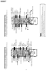
DV-NV70U/C DV-NC72U DV-NC70U/C DV-NC72U 12. SCHEMATIC DIAGRAMS 12-1.
DV-NV70U/C DV-NC72U DV-NC70U/C DV-NC72U 12-2.
DV-NV70U/C DV-NC72U DV-NC70U/C DV-NC72U 12-3.
DV-NV70U/C DV-NC72U DV-NC70U/C DV-NC72U å AND SHADED COMPONENTS=SAFETY RELATED PARTS 12-4.
DV-NV70U/C DV-NC72U DV-NC70U/C DV-NC72U 12-5.
DV-NC70U/C DV-NC72U 12-6.
DV-NC70U/C DV-NC72U 12-7.
DV-NV70U/C DV-NC72U DV-NC70U/C DV-NC72U å AND SHADED COMPONENTS=SAFETY RELATED PARTS 12-8.
DV-NV70U/C DV-NC72U DV-NC70U/C DV-NC72U 13.
DV-NV70U/C DV-NC72U DV-NC70U/C DV-NC72U J DVD MAIN PWB SIDE B R3 3 1 0 R3 3 1 1 Q3 3 0 2 C3 3 0 2 C3 3 0 1 T P3 3 T3 P3 3 332 RJ 3 1 0 5 R3 3 2 0 R3 3 2 1 Z4 R3 3 2 3 R3 3 2 5 C3 3 0 3 Z1 C3 3 3 0 D3 3 0 1 Q3 3 0 4 R3 3 2 4 C3 3 1 1 R3 3 1 7 Z2 Q3 3 0 3 C3 3 4 3 C3 3 4 4 C3 6 1 8 C3 6 1 9 C3 6 2 0 R3 6 0 6 R3 6 0 7 C3 3 4 6 R3 3 2 2 F B3 3 0 1 R3 3 0 6 R3 3 0 5 C3 3 3 3 C3 3 3 1 R3 8 0 9 R3 8 1 0 C3 8 0 9 R3 8 0 5 C3 6 2 5 R3 6 1 6 C3 6 2 6 R3 6 1 7 C3 6 2 7 C3
DV-NC70U/C DV-NC72U DVD OPERATION PWB SIDE A Symbol J SIDE B I H G F E D C B A 1 2 3 4 5 6 78 7 8 9 10
DV-NC70U/C DV-NC72U VCR OPERATION PWB SIDE A Symbol J SIDE B I H G F E D C B A 10 1 11 2 12 3 13 4 14 5 15 6 79 16 7 17 8 18 9 19 10
DV-NV70U/C DV-NC72U DV-NC70U/C DV-NC72U J POWER PWB SIDE A Symbol I H G F E D C B A 1 2 3 4 5 6 7 8 9 10 11 80~81 12 13 14 15 16 17 18 19 20
DV-NV70U/C DV-NC72U DV-NC70U/C DV-NC72U J POWER PWB SIDE B I H G F E D C B A 1 2 3 4 5 6 7 8 9 10 11 82~83 12 13 14 15 16 17 18 19 20
DV-NV70U/C DV-NC72U DV-NC70U/C DV-NC72U J VCR MAIN PWB SIDE A Symbol I H G F E D C B A 1 2 3 4 5 6 7 8 9 10 11 84~85 12 13 14 15 16 17 18 19 20
DV-NV70U/C DV-NC72U DV-NC70U/C DV-NC72U J VCR MAIN PWB SIDE B I H G F E D C B A 1 2 3 4 5 6 7 8 9 10 11 86~87 12 13 14 15 16 17 18 19 20
DV-NC70U/C DV-NC72U -MEMO- J I H G F E D C B A 1 2 3 4 5 6 88 7 8 9 10
DV-NC70U/C DV-NC72U 14. REPLACEMENT PARTS LIST/ Part No. ★ Description Code EXPLODED VIEWS Ref. No. Ref. No. ELECTRICAL PARTS LIST Parts marked with " å " are important for maintaining the safety of the set. Be sure to replace these parts with specified ones for maintaining the safety and performance of the set. Les pièces marquéss " å " sont importantes pour maintenir la sècurité de l'appareil.
DV-NC70U/C DV-NC72U Ref. No. Part No. ★ Description Ref. No.
DV-NC70U/C DV-NC72U Ref. No. Part No. ★ Description Code Ref. No.
DV-NC70U/C DV-NC72U Ref. No. ★ Part No. Description Ref. No. Code DUNTKB209TE6E DVD MAIN PWB UNIT(Continued) Part No.
DV-NC70U/C DV-NC72U Ref. No. ★ Part No. Description Code Ref. No.
DV-NC70U/C DV-NC72U Ref. No. Part No. ★ Description Ref. No.
DV-NC70U/C DV-NC72U Ref. No. Part No. ★ Description Code Ref. No.
DV-NC70U/C DV-NC72U Ref. No. Part No.
DV-NC70U/C DV-NC72U Ref. No. ★ Part No. Description Code Ref. No.
DV-NC70U/C DV-NC72U Ref. No. ★ Part No. Description Ref. No. Code DUNTKB213TEV2 POWER PWB UNIT(Continued) C928 C929 C932 C935 C936 C937 C938 C939 C944 C945 C946 C948 C949 C950 C952 VCQYTA1HM104K+ VCEA0A2AW106M+ VCEA0A1EW108M+ VCEA0A1AW228M VCEA9M1HW105M+ VCEA9M0JW476M+ VCEA9M1HW105M+ VCEA9M0JW476M+ VCEA0A1HW107M+ VCEA9M1CW107M+ VCEA9M1HW225M+ VCEA9M0JW227M+ VCEA9M1HW105M+ VCEA9M0JW476M+ VCEA9M1CW226M+ 0.1 10 1000 2200 1 47 1 47 100 100 2.
DV-NC70U/C DV-NC72U Ref. No. Part No.
DV-NC70U/C DV-NC72U Ref. No. Part No. ★ Description Ref. No.
DV-NC70U/C DV-NC72U MECHANISM Ref. No. Part No. EXPLODED VIEW (DVD PART)Ref. No. ★ Description Code ★ Part No. Description Code Dry Coating H Dry Coating Dry Coating 434 G 429 432 Dry Coating F 433 431 Grease 435 E Grease 428 427 425 426 401-11 420 401-13 424 D Grease Grease 401-4 401-10 401-12 401-3 401-2 422 423 409 421 C Grease 419 418 401-5 410 409 409 B 401-9 å Caution When touching the pickup, wear an earth band to prevent breakage by static electricity.
DV-NC70U/C DV-NC72U Ref.MECHANISM No. Part No.EXPLODED ★ Description VIEW (VCRCode PART) Ref. No. ★ Part No.
DV-NC70U/C DV-NC72U Ref.CASSETTE No. Part No. ★ HOUSING Description EXPLODED Code Ref. No. CONTROL VIEW ★ Part No.
DV-NC70U/C DV-NC72U Ref.CABINET No. Part No. ★ EXPLODED Description VIEW 57 Ref. No. Code Description Code 56 2 56 52 H ★ Part No.
DV-NC70U/C DV-NC72U Ref.FRONT No. Part No. PANEL ★ Description EXPLODED VIEW Code Ref. No. ★ Part No.
DV-NC70U/C DV-NC72U Ref. PACKING No. Part No. ★ Description 15. OF THE SET Ref. No. Code Part No. ★ Description Code ★ SSAKA0001AJZZ (Operation Manual Polyethylene Bag) RRMCGA053WJSA (DV-NC70U/C) RRMCGA053WJSB (DV-NC72U) (Remote Control unit) TGAN-3324AJZZ (DV-NC70U) (Guarantee Card) TiNS-A121WJZZ (DV-NC70U/72U) TiNS-A122WJZZ (DV-NC70C) (Operation Manual) QCNW-8387AJZZ (RF Cable) ★ SPAKP0209AJZZ (Wrapping Paper) QCNW-8388AJZZ (AV Cable) ★ SPAKXA023WJZZ (Packing Add.) ★ TLABV0182AJZZ (No.
DV-NC70U/C DV-NC72U Ref. No. Part No. ★ Description Code Ref. No. 107 Part No.
DV-NC70U/C DV-NC72U Ref. No. Part No. ★ Description Ref. No. Code Part No. ★ Description Code COPYRIGHT © 2002 BY SHARP CORPORATION ALL RIGHTS RESERVED. No part of this publication may be reproduced, stored in a retrieval system, or transmitted in any form or by any means, electronic, mechanical, photocopying, recording, or otherwise, without prior written permission of the publisher.