
Cash Register User Manual


ER-A520U/ER-A530U DIAGNOSTIC PROGRAM
– 19 –
13) CPU INTERNAL RAM TEST
1
Key operation
122
3
2
Test procedure
The test program tests internal RAM (10 Kbytes) of the CPU.
The contents of memory must be stored before and after this test.
RAM (00400H ~ 02BFFH area) is tested in the following procedure.
a) Store data in the test area.
b) Write “00H”
c) Read and compare “00H” and then write “55H”
d) Read and compare “55H” and then write “AAH”
e) Read and compare “AAH”
f) Restore stored data
If an error occurs at a step, the error is printed.
If any error does not occur, the following addresses are checked
in turns.
Addresses to be checked:
01000H, 01001H, 01002H, 01004H, 01008H
01010H, 01020H, 01040H, 01080H,
01100H, 01200H, 01400H, 01800H,
02000H
3
Check:
The completion print.
4
End of testing
If an error occurs, the printer outputs the error message and the
address where the error has occurred in the area
*****
.
14) FLASH ROM TEST
1
Key operation
130
3
2
Test procedure
The test program checks that the checksum of the flash ROM
(F00000H ~ FFFFFH).
The lower two digits of the checksum should be 10H. (pending)
3
Check: The completion print.
4
End of testing
The test will automatically be terminated and the printer prints as
follows:
15) AD CONVERSION PORT TEST
1
Key operation
160
3
2
Test procedure
The test program displays the voltage of each AD conversion port.
3
End of testing
You can exit the test mode by pressing any key. The printer prints
the following.
160
16)POLE DISPLAY TEST
UP-P16DP is attached in DISPLAY CN.
1
Key operation
400
3
2
Test procedure
Displayed in the following procedure A test pattern.
Progresses to the following pattern by pushing arbitrary KEY.
i ) The following test pattern is displayed.
ii) The test pattern of all beam all-points lights is displayed.
3
Check:
A) The display of each position is right.
B) Be uniform in the luminosity of each display and there needs to
be no MURA in it.
4
End of testing
You can exit the test mode by pressing any key. The printer prints
the following.
400
17) RS232 CH1 TEST
Install the RS232 loopback connector.
1
Key operation
500
3
2
Test procedure
The test program checks the control signals.
The test program ends after printing.
When the test ends normally: 122
When the test ends abnormally: Ex – ~ – 122
*****
x = 1: Data error
x = 2: Address error
When the test ends normally: 130
ROM
****** **
(Model name)
****** **
(Version)
When the test ends
abnormally:
E
– – ~ – –
130
ROM
****** **
(Model name)
****** **
(Version)
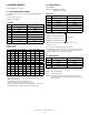
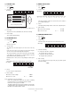
CA/AT
RAMCPU
SRV
OP display
122
CA/AT
ROMFLASH
SRV
OP display
130
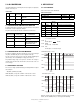
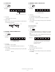
OUTPUT INPUT
/ER1 /RS1 /DR1 /CI1 /CD1 /CS1
OFF OFF OFF OFF OFF OFF
OFF ON OFF OFF ON ON
ON OFF ON ON OFF OFF
ON ON ON ON ON ON
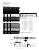
CA/AT
TM
SRV
OP display
Display
160
=
VRF
SRV
OP display
160
=
VPTEST
SRV
OP display
160
=
Repeat
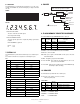
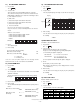
CA/AT
DOT DISPLAY
7SEG DISPLAY
0123456789;AaBbC
0.1.2.3.4.5.6.7.8.9.-.
:
:
ccccccccccc
CA/AT