E2?m/@: SHARI= SERVICE MANUAL No. OOZU22OCMUShIEI FACSIMILE MODEL / UX-2200CM FO-2150CM CONTENTS CHAPTER 1. GENERAL DESCRIPTION [l] Specifications ............................................ [2] Operation panel.. ....................................... [3] Transmittable documents .......................... [4] Installation ................................................. [5] Quick reference guide ............................... l-1 1-2 l-3 l-4 l-9 CHAPTER 2. ADJUSTMENTS [l] Adjustments.. ........
- CAUTION FOR BATTERY REPLACEMENT ADVARSEL I (Danish) Lithiumbatteri-Eksplosionsfare ved fejlagtig handtering. Udskiftning ml kun ske med batteri af samme fabnkat og type. Lever det brugte batteri tilbage til leverandoren. (English) Caution I Danger of explosion if battery is incorrectly replaced. Replace only with the same or equivalent type recommended by the equipment manufacturer. Discard used batteries according to manufacturer’s instructions.
CHAPTER I. GENERAL DESCRIPTION [l] Specifications Copying specifications Printing specifications Resolution Print cartridges Color: Sharp UX-27CC Black:Sharp UX-22BC Print resolution High:600 x 600 dpi (both color and black) Normal : 300 x 300 dpi Print speed Color: Up to 2 pages per minute Black: Up to 3 pages per minute Paper types Index cards, envelopes, labels, transparencies, glossy film, greeting cards, iron-on transfers, plain, coated, and glossy paper.
UX22OOCMU~~C Fo-21gocrvlu/cMc [2] Operation panel cO10r Multifunction ,_-______-_____---__--. 0 @ SPEED DIAL key Press this key to dial a 2digit REDlALkey Press this key to automatically 0 SPEAKERkey Press this key to hear the line and fax tones through the speaker when sending a document. Note:This is not a speakerphone. You must pick up the handset to talk with the other party.
[3] Transmittable 5. Automatic Document Feeder Capacity documents Number of pages that can be placed into the feeder at anytime is as follows: 1. Document Sizes 1 1 width Normal size length 5.63”~8.5”(146 Normal size: max. ADF 20 sheets (14 Ibs - 20 Ibs) - 216 mm) Special size: single sheet only (manual feed) 5.04”-11”(126-297mm) NOTES: l When you need to send or copy more pages than the feeder limit, place additional pages in feeder when last page in feeder is being scanned.
7. Use of Document A document TELEPHONE Carrier Sheet carrier sheet must be used for the following documents. Those with tears. l Plugging the fax machine into a jack which is not an RJll C jack may result in damage to the machine or your telephone system. If you do not know what kind of jack you have, or needed to have one installed, contact the telephone company. Those smaller than size 5.83”(W) x 5.04”(L) (148 mm (W) x 128 mm (L)).
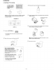
ux-22oocMuIcMc FO-215ocMuKMc 3. Connections 0 @ Handset Insert one end of the line cord into the jack on the back of the machine marked TEL. LINE. Insert the other end into a standard (RJllC) single-line wall telephone jack. Connect the handset as shown and place it on the handset rest. + The ends of the handset either jack.
uxs2goCMuKJMc Fo-215oCMu/Ch,K 4. Installing a Print Cartrige .-f----l Your Sham Color MFP uses either a UX-27CC cOlorprint cartridge or a \ UX-22BC black print iI cartridge. - 1’ We recommend that you keep a black cartridge installed for normal use, and change to a color cartridge only when you need to print a color job. L-~ 0 Remove the new print cartridge from its packaging.
UX-ZZOOCMU/CMC FO-215ochIu/cMc 5. Loading Printing Paper @ You can load letter or legal size paper in the paper tray. The maximum number of sheets is: Press the START key. 4 266for paper from 16 to 20 Ibs. (60 to 60 g!m2) l The display on the Sharp Color MFP will show: SELECT CARTRIDGE 15Ofor paper from 20 to 24 Ibs. (90 g/m2) (such as coated paper) @ Remove the paper cover if it is on the paper tray. Press 1 if you installed a new cartridge, or 2 if you installed an old cartridge. .
ux-22oOcMUt~c FO-215ocMu/cMc 0 Clearing jammed prlnlng paper The Sharp Color MFP has been set at the factory to scale the size of received faxes to letter size paper. If you have loaded legal paper, you must change the paper size setting to legal. Press these keys: The display will show: 1PAPER SIZE @ Open the front cover of the Sharp MFP. I Presst to select LETTER,2 to select LEGAL, or 3 to select A4. LETTER: @ LEGAL: 0 A4: @ Q Press the STOP key to return to the date and time display.
ux-22o0cMu/cMc FG-215ocMuKhK [5] Quick reference 1. Press: guide 1. Place the document (up to 20 pages) face down in the document feeder. CARTRIDGE r-r I 1 2. Open the front cover of the Sharp Color MFP. 2. If you are copying onto a transparency or special paper, flip up the original document output support and insert the media into the manual paper feeder. 3. Remove the current print cartridge. l If the cartridge is still useable, insert it in the holder on the back of the machine.
ux-22OoCMu/Ch,rc lQ21m/cMc 1. Press: Place the document (up to 20 pages) face down in the document feeder. FUNCTION II@@ Display shows: FAX/TEL Normal Dialing # MODE 1. Lift the handset or press SPEAKER 0 2. Press 1 to store a number or 2 to clear a number. 2. Dial the fax number. 3. Enter a P-digit Speed Dial number (from 01 to 36 for Rapid Key Dialing, or 39 to 99 for Speed Dialing). (If you are clearing a number, go to Step 7.) 3.
CHAPTER 2. ADJUSTMENTS (1) Fl (ICPSO7) is installed in order to protect It’s from an over-current generated in the motor drive circuit. If Fl is open, replace it with a new one. [l] Adjustments 3. Settings General (1) Dial mode selector Since the following adjustments and settings are provided for this model, make adjustments and/or setup as necessary. DIAL mode (Soft Switch No. SW2 DATA No. 1) (step 1) Select “OPTION SETTING”. 1.
UX--/CMC! lW-215oCMu/cMc [2] Diagnostics and service soft switch 1. Operating procedure (1) Enterlng the diagnostic mode Press w[ --f q + q -tm +m 1ROM Ver. FBSOX: FBSlm +a , and the following display will appear. /After 2 set: -1 FBSO m : FBSl m Then press the m key and country name selected by country select will appear. Select the desired item with the H key or the with the rapid key. Enter the mode with the START key qkey or select (Diagqecifications) m-*@@@@@ 4 Ver.
UX-22oocMu/cMC FC-215OCMLJ/CMc 3. Diagnostic items description 3.3. Aging mode 3.1. Soft switch mode If any document is first present, copying If no document is present, the check sheet. This operation will be executed utes, and will be ended at a total of 10 In this mode, the soft switch are set and the soft switch list is printed. Soft switch mode screen. 3.4. Panel key test The mode is used to check whether each key properly operates or not.
UX-22oocMu/cMC Fo-216ccMu/CMc 3. 7. Memory clear This mode is used to clear the backup memory and reset to the default settings. 3.8. Shading mode This mode is used to store the shading waveform specified shading document. according to the 3.9. All black print This mode is used to check the state of the printing head and intentionally overheat it. Press STOP key for the end. 3.10. Auto feeder mode This mode is used to check the auto feed function by inserting and discharging the document.
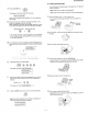
UX424WCMUlCMC FQ-215ocMulcMc 4. How to make soft switch setting To enter the soft switch mode, make the following key entries in sequence. DATA No. 12345678 1 1 .SFT SFT SW-1 =:+I =,,.o,. 0 0 00 0 0 0 001 0 01 J SFT SW-1 =I:@ 0 00 0 00) 1 Press [FUNCTIONI key. ~ Press I#1 key. 1 SFT SW-1 = ,,I 0 0 00 0 00) Il Press Bit1 - 8 are set. : 1 SFT SW-l = 1 0 0 0 0 0 q key. 0 /@] Press ISTART] 1 SFT SW-l = .
ux-22oocMu/cMC ln215ocMu/~c 5. Soft l switch description Soft switch Binary input 8 1 No.= 4 2 1 2 3 4 Binary input 8 No. = 5 4 2 1 6 7 8 Binary input 8 1 No.= 4 2 1 2 3 4 Binary input 8 No.
UXCZOOCMU~CMC FD21-/cMc SW NO. DATA NO. Switch setting and function ITEM 1 0 initial setting 1 H2 mode No Yes 0 2 MH fixed Yes No (depend on remote machine) 0 3 Reserved - - 0 4 Reserved - - 0 Modem speed v.33 14400 12000 (DCS data reception speed) No.5 0 No.6 1 1 No.7 0 1 0 0 No.8 v.17 8 v.29 0 V.27ter 96007200 48002400 14400 12000 No.5 1 1 1 1 0 0 0 No.6 0 0 0 0 0 0 00 96007200 0 1 0 No.7 0 1 0 1 0 1 1 0 0 No.
TJX22OOCMUlCMC F0215OCMsJ~CMc SW NO. - DATA NO. Switch setting and function ITEM 1 END Buzzer SW I 11 SW Initial setting 0 3sec 1set No BEEP 1 No.1 0 0 1 1 0 2 No.
Hand-set receiver volume (astages) when Fine/STD mode) I !2 4 5 6 Reserved Reserved Copy Ratio for S/VI copy - 0 - - No.6 0 AUTO 100% 0 0 FUNC+G 0 7 No.7 0 0 1 6 No.
UX-22OOCMUiCMC Fo-216OcMu/cMc Switch setting and function ITEM 1 2 1 ( Resewed 1 Resewed 0 Resewed - - Resewed - - 0 - - 0 ; I 23 5 Resewed 6 1 Resewed - - 7 1 Resewed - - - Binary input 16 No. = 4 5 4 2 1 1 1 1 1 (15) 1 1 Yes No 0 Yes No 0 6 FAX printing when low ink detected Yes No 0 1 Align cartridge (l-30) FUNC+G 0 for black cartridge 2 Binary input 16 3 No.
7 ( ReSeWed 8 Resewed 1 2 3 SW ’ 30 4 5 I - - 0 0 Quiet detect time Binary input 8 No. = 1 0 4 2 1 1 2 3 1 4 0 0 (4sec) 0 0 0 Quiet detect start timing 1 1 8 1 (5sec) - 0 6 7 Binary input 8 No.
l Soft switch function description SW1 No. 1 - No. 4 Recall interval Choice is made for a recall interval for speed and rapid dial-numbers. Use a binary number to program this. If set to 0 accidentally, 1 will be assumed. SW1 No. 5 - No. 8 Recall times Choice is made as to how many recall attempts a binary number to program this. should be made. Use SW2 No. 1 Dial mode Switch the type according to the telephone facsimile. 1 : PULSE DIAL 0 : TONE DIAL circuit connected to the SW2 No.
UX-22OOCMUlCMC Fo-215OCMtJcMc SW4 No. 5, No. 6 Delay timer of after line connect in auto dial Delay time between the line connection and dial data output under the auto dial mode. RAPID01 CML RELAY ON v V I- DIAL DATA- -l mode) SW7 No. 5 EOL defect Used for detection of CNG in 1 to 4 pulses. timer Used to make a choice of whether to use the 25second or 13-second timer for detection of End of line.
LJX-22oocMu/cMC Fo-215clcMu/cMc SW9 No. 8 Bwy SW11 No. 1, No. 2 End buzzer tone detection (after auto dial) Use to set busy tone detection in auto dialing. The sounding SW10 No. 1, No. 2 Resewed SW11 No. 3 Communication error treatment in RTN sending mode (reception) set to ‘0”. SW10 No. 3, No. 4 Cl oft detection timer (Distinctive ring setting off only) Set the minimum time period of Cl signal interruption which affords to be judged as a Cl OFF section. I-B-I +------I 1 l-l t-l 4oomsac SW11 No.
UX-ICMC FO-215Oc!hIuK!Mc SW17 No. 1, No. 2 Speaker volume (3stage~r) SW19 No. 6 MTF correction in Half-tone mode Speaker volume: The sound volume of the speaker in the on-hook mode is set. This allows selection of MTF correction (dimness correction) in the half tone mode. When “Strong” (= 1) is selected, the whole image becomes soft and mild, On the contrary, however, clearness of characters will be reduced. Normally set to “Strong” (= 1). SW17 No. 3, No.
SW24 No. 8 Fax printing when low ink detected To print the received picture in “Low Ink” state, set “1’. SW28 No. 2, No. 3 Busy tone detection ON/OFF time (Longer duration) SW25 No. 1 - No. 5 Align cartridge (l-30) for black cartridge Similarly to SW-28 No.1, the set value can be varied. The upper limit can be set in the range of 65Omsec to 2700msec. After the black cartridge has been mounted press “FUNCTION”, “8, %“, “H”, x’, SW28 No.
UX?22WCMU~CMC F+o-215ocMu/cMc [3] Troubleshooting Refer to the following actions to troubleshoot any of problems mentioned in 14. Apply line equalization SOFT SWITCH 8-1, 2. May be used in case [l] [2] [3] [4]. [l] A communication [2] Image distortion produced. [3] Unable to do overseas communication. Replace the TEULIU [4] Communication May be used in all cases. l l error occurs. Slow down the transmission speed SOFT SWITCH 6-5, 6,7,8. May be used in case [2] [3].
ux-m/cMc IV-215OCMuKMc [4] Error code table 1. Communication error code table G3 Transmission Code Final received signal Error Condition (Receiver side) 0 Incomplete signal frame 1 NSF, DIS Cannot recognize DCS signal by echo etc.
CHAPTER 3. MECHANISM BLOCKS 3-2. Automatic [l] General description 1. Document document feed 1) Use of the paper feed roller and separation rubber plate ensures error-free transport and separation of documents. The plate spring presses the document to the paper feed roller to assure smooth feeding of the document. 2) Document separation feed block and diagram J%=r method: Separation rubber plate ,,!%parator feed spring rubber Separator rubber Paper feed spring I Fig. 3 3-3.
5. Paper feed 3-5. Documents requiring use of document carrier 1) Documents smaller than B6 (126mm x 162mm). 2) Documents 5-1. ASF thinner than the thickness of 0.06mm. As a result of reception motor drive the reduction gear, idler gear, planetary gear, and paper feed gear are synchronized. Since the Pu roller rotates, the paper sensor is turned on and advanced until it engages with the feed roller, Then, the motor is inverted to feed to the print position with the feed roller.
5-4. ASF sequence CPU ASIC HOST Paper Load CMD (ASF) INT2 \ 5 Busy EE Not Busy Not Busy r, C Pass 1 : For Paper load Steps : 494.2mm Set Control Register 4 Direction : Reverse Feed Motor Moving 0 Polling : Paper sensor If “Paper sensor”= On Then Goto INTl > Goto Paper OUT State Stop of Feed Motor < Pass 2 : For Skew Set Control Register Steps : 8.5mm < ( Direction : Reverse Feed Mot,or Moving k LT, , Pass 3 : For Top position Set Control Register Steps : 8.
ux-224mcMu~cMc m-215ocMu/cMc [2] Disassembly l l and assembly This chapter mainly describes the disassembly Easy and simple disassembly/assembly procedures procedures. procedures For the assembly procedures, reverse the disassembly of some parts and units are omitted. For disassembly procedures. and assembly of such parts and units, refer to the Parts List.
2 Left Cabinet, Right Cabinet, Front cover Disa! iembly procedures (Fig. 2) REMOVAL PROCEDURE Left Cabinet 1 Right Cabinet 1 1.Screw 1. Screw (3x12) .... .... ... ... ... ... ... ..... ... (Al) x 2 2. Release the Left Cabinet lock nails ........ @ (3x12) ................................ (El) x 1 2. Release the Right Cabinet lock nails.. .... . Front Cover 1. Push inside the Front Cover arms.. ......... @ Cabinet Front Cover Fig.
ux-22oocMu/cMC Fo-215ocMu/cMc 3 Operation panel Unit Disassembly procedures (Fig. 3) STEF REMOVAL Operation Panel Unit Panel Cabinet PROCEDURE 1. Push the Ooeration Panel Unit arms . a 1. Screw (3x10) ... .. ... .... ... ...... ......... . (81) x 3 2. Socket .......................................... (82) x 1 3. Push the Upper Document Guide arms .@ Panel PWB Unit, IPKey, 1. Screw (2x6) .................................. (Cl) x 6 Direct Key, Start Key, 2. Push outside the LCD PWB Hook.. .........
UX-22OOCMUlCMC Fo-215ocMu/cMc 4 I Paper Feed Cabinet Disassembly procedures (Fig. 4) STEP REMOVAL 1 Paper Feed Cabinet 2 Paper Feed RollerHolder 3 Paper Up Roller A&y 4 I1 PROCEDURE I. Screw (3x10) ..... ... ..... .......... .... .... (Al) x 2 1. Screw(3x10) . ................... .... ... ... . (81) x 2 1. Remove the Paper Feed Gear 2. Pull forward the shaft holder .. ... ...... ..... ....@I 3. Remove the Paper Up Roller Shaft Paoer Feed Frame I 1. Screw (3x10) ................................
5 Upper Document Guide Disac embly procedures (Fig. 5) b I I--T . 1 I1 . .. ... ... ..... ......... ... ... ........ . (AZ) x 1 3 5 Pinch Roller 1. Screw (3x13).................................. (A4) x 1 Document Out Spring 1. Remove spring ....................................... f@ Panel Lock Lever t- 2. Remove the Panel Lock Lever ............... @ 6?l 0 Strength Angle (A3bQ X\ PinchYRoller “f@ ‘Upper Dot. Guide pk Fig.
6 Lower Document Guide, CIS Unit ... ... .. ... .... ....... .... .... .. 3. (Al)xl CIS Hqlder Fig. 6 ...... ..... .... . .... .... ..... ..... ..... ...
UX-225OCMUlCMC m-215ocMu/cMc 7 Drive Unit, Printer Unit Disassemblv orocedures IFia. 7) STEP REMOVAL PROCEDURE 1 GroundCable 1. Screw (3x4) .................................. 2 Drive Unit 1. Screw (3x10) ................................ (Bl) x 2 2. Gear (16/35z) ............................... (82) x 1 3. Socket .......................................... (83) x 1 (Al) x 1 4. Gear (16/36z) ............................... (B4) x 4 5. Screw (3x10) ................................
m-22oocMu/cMc Fo-215ocMu/cMc 8 Scaner Unit Disassembly STEP procedures REMOVAL (Fig. 8) PROCEDURE 1.Remove the Transfer Roller 1 Transfer Roller 2 Feed Roller I. Screw (3x30) . ..... ......... ..... ..... ... ... (Al) x 1 3 Extension Hopper 1. Slide the Extension Hopper 4 Sub Base Plate I I 1. Push the Sub Base Plate latch ........ ..... ..@ 2. Slide the Sub Base Plate ............ ......... ...@ (Al)xl / N Pushandbend the Extension Roller 1 Hopper. ‘Base Plate Fig.
ux-22oocMu/cMc FO-215ocMu/cMc 9 I I Printer Unit 2 Disassembly procedures (Fig. 9) Holder.. ......................................... 1. Socket . .. ... .... ..... ...... ... ........... ... .... 2. screw (3x4) ..... ..... .. ........... .. ... .. ... . (C2) x 2 4 1Maintenance Base 5 Motor Bracket 1. Motor Bracket nter PWB Unit Feed Belt’ Ink PWB (E3)xl Maintenance Fig. 9 3-12 1 1. Screw (1x6) .................................. (Dl) x 1 1. Screw (3x6) ..................................
10 IrDA PWB Unit, Control PWB Unit, TEULiu PWB Unit, Power Supply PWB Unit Disassembly procedures (Fig. 10) STEP REMOVAL 1 IrDA PWB Unit PROCEDURE 1. Socket .......................................... (Al) 1 x 1 2. screw (3 x 10) .............................. (A2) x 1 2 Speaker A&y 1. Socket .......................................... (Bl) x 1 2. Screw (3 x 10) .............................. (82) x 3 3 Control PWB Unit 1. Screw (3 x 10) .............................. (Cl) x 7 TEL/Liu PWB Unit 2.
UX-22OOCMUlWC Fo215och4u/cMc 11 Parts list (Fig. 11) I Wire treatment m] Panel PWB Cable and CIS Cable \ 2 Motor Bracket’s Cable pass the coil 2 turns Scanner Cable Earth Cable from Motor Bracket Make sure cables not come out from Rib IrDA Cable Panel PWB Cable pass the coil 3 turnes Sensor Cable pass CIS Cable pass the coil 2 turnes Speaker Cable pass the coil 1 tumes Fig.
UX-22oocMuIcMC m-z15ocMu/cMc CHAPTER 4.
- SPEAKER IF HANDSET c I 1 TEULIU PWB UNIT CNSP PHOT SENSOR PWB CNPHOT(RED) I 1,L 36 CNPC L To PC A TEZ.
0 I P [3] Point- to-point diagram PANEL PWB PWB I TELJLIU :NUUA CONTROL PWB (l/2) : I5 ?3-!7 !S !Q Y)II !2-)3Y)5*-- ‘3 ‘4 - 2- ,- cl- 2- 5- 7- 8- 5- I- 3- Z- 1- I-- CNP( PWB POWER SUPPLY
P I P [3] Point- to-point diagram BAI-IERY BAT+ SOCKET MT_ PANEL UNIT PWB ---________ 3NLlUB NM. .
m-22oocMu/cMc Fo-21i50c!MuKMc 3. Operational description CHAPTER 5. CIRCUIT DESCRIPTION Operational descriptions are given below: Transmission operation [l] Circuit description When a document is loaded in standby mode, the state of the document sensor is sensed via the CPU (SHZ). If the sensor signal was on, the motor is started to bring the document into the standby position. With depression of the START key in the off-hook state, transmission takes place. 1.
UX-22oocMu/cMC MT215tXNfJCMc [2] Circuit description of control PWB 2) M27C4001 (IC18, IC19): pin-32 DIP (ROM) EPROM of 2Mbit equipped with software for the main CPU. 1. General description 3) SRM2B257SLMX70 Fig. 2 shows the functional posed of 5 blocks. Line memory for the main CPU system RAM area and coding/decoding process. Used as the transmission buffer. blocks of the control PWB, which is com- (IC17, IC24): pin-28 SOP (RAM) Memory of recorded data such as daily report and auto dials.
SH7040 (IC12) Terminal list 7 - MCU MODE PROM MODE Pin No. 1 ‘El 4/TlOC4C/DACKO/AH vcc 60 PD8/D8 2 ‘E15/TIDC4D/DACKl/IRQDUT CE 61 vss QFPl12 Pin No. MCU MODE - PROM MODE N.C. vss vss 62 PD7iD7 D7 4 PCO/AO A0 63 PD6/D6 D6 5 PCl/Al Al 64 PD5/D5 6 Pa/A2 A2 65 vcc 3 vss D5 vcc 7 PC3/A3 A3 66 PD4/D4 6 PC4/A4 A4 67 PD3/D3 D3 9 PC5lA5 A5 66 PD2/D2 D2 Dl D4 10 PC6fA6 A6 69 PDl/Dl 11 PC7/A7 A7 70 PDO/DO 12 Pm/A6 A6 71 vss 13 PC9/A9 N.C.
UX-22oocMu/cMC m215ocMu~cMc SH7040 (IC12) Terminal function Connect the Vcc terminal to the power of all systems. nal to the ground of all systems. Operation System control Power-on reset is not performed if there is open terminal. When Low Level is applied to this terminal, During operation do not change the input value. Bus control the external space is made.
SH7040 (IC12) Terminal function Function Classification Symbol Input/Output Name Bus control CASH output High-order column DRAM column address strobe timing signal. It is output when access to high-order Bbits of data is made. address strobe Multifunction timer pulse unit Direct memorv access controller (DMAC) Serial communication interface (SCI) A.D converter CASL output Low order column address strobe DRAM column address strobe timing signal.
UX-22oocMu/cMC Fo-21EQCMu/CMc SH7040 (El 2) Terminal function Classification Symbol Input/Output Name I/O port POE0 - POE3 Input Port output enable Input terminal to perform port terminal drive control when the general-use port is set to output. PA0 - PA15 (QFP-112) PA0 - PA23 (QFP-144) Input/output General use port General-use input/output port terminal. It is possible to specify input/output for each bit. PBO - PBQ Input/output General use port General-use input/output port terminal.
(2) Panel control block The following controls are performed l Operation panel key scanning l Operation panel LCD display by the Gate array (KQFJ49). (3) Mechanism/recording control block The following controls are performed by Gate array (LZQFJ49). l TX Motor control The following controls are performed by CPU (SK?). l Sensor detection The following controls are performed l l by Gate array (TCl60G33:PRINTER PWB).
UX-22oocMu/cMC Fo-215OCMU/CMc (4) Modem (Rl44EFXL) FEATURES block . INTRODUCTION Group 3 facsimile transmission/reception - ITU-TS V.29, V27 ter, T.30, V.21 Channel 2, T.4 The Rockwell R144EFXL MONOFAX modem is a synchronous 14400 bits per second (bps) half-duplex modem with error detection and DTMF reception. It has low power consumption and requires only a single +5V DC power supply. The modem is housed in a single VLSI device package.
Rg6DFXL-CID (ICll) Pin No. Hardware Interface Signals Signal Name 110 Type 1 GP93 IA/O6 60 RSO IA 2 GPCM MOB 61 GP13 IAIOB Pin No.
(5) Image signal process block y~~Tq--J~ Fig. 5 The CIS is driven by the LSI (LC82103), and the output video signal from the CIS is input into the LC82103 through the amplifying circuit. The ADC and buffer are provided in the LC82103, and the digital image processing is performed. (6) Speaker amplifier The speaker amplifier monitors the line under the on-hook mode, outputs the buzzer sound generated from the SH7040, ringer sound, DTMF generated from the modem, and line sound.
ux-22-~~c FD-215OCMu/CMc [3] Circuit description (1) TEL/LlU of TEULIU block operational PWB description 1) Block diagram Fig. 6 2) Circuit description 3) Block description The TEULIU 1. Surge Protection circuit PWB is composed of the following 10 blocks. This circuit protects the circuit from the surge voltage occurring on the t818phOn8 line. 1. Surge protection circuit 2. On-hook status detection circuit l 3.
UXCZXOCMUICMC m2l~lcMc 2. On-hook etetus detection circuit 7. Signal selection The on-hook status detection circuit detects the Status of the hook switch (RHS) of Built-in telephone, and the status of the hook of a telephone externally connected. l The status of on-hook switch (RHS) is determined level of RHS signal. RHS LOW RHS HIGH l from the logical The following signals are used to control the transmission line of TEL/ FAX signal. For details, refer to the signal selector matrix table.
m-22oocMu/cMc Fo-215och,ru/cMc [Signals for status recognition according to input signals] Signal Name RHS NO Function ) Signal Name (CNLIU) ] NO ] Signal Name (CNLtU) 1 +24VA 6 RHS 2 DG 9 TXOUT L: The handset is in the off-hook state. 3 PE 10 incoming call (Cl) detection signal. 4 +5v 11 5 CML 12 NC. 6 Cl 13 TELOUT 7 HS 14 TELIN H: The handset is in the on-hook state.
UX-22oocMu/cMC I0215oCMUCMc [4] Circuit description of power supply PWB 1. Block diagram TRANSFORMER SWITCHING 1 1 Fl ACIN 0 12ov 0 4.OA 125V w RECTITYING +5v 50/6OHZ GND +24V _ CIRCUIT - +24V A Fig. 8 trol circuit through the photo coupler PC1 from +24V output. The overcurrent-protective circuit detects that the ON period becomes the wider as the output load becomes the heavier.
CHAPTER 6.
-l M27C4001-10Fl F I \ 0 I ‘00 07 - WRL 12 22 20 27 Do cl, 13 1, 03 02 15 TCSl (I-2E) aps1, (5.
I 0 ul 4 - 5 - I3 I (5.2H) a 4 12 5 7 3 14 B 8 8 10 1, IC3 4066 Reading block A +W a25 0.1 a I + I3178 4. 1 C A’N D102 DAZO4K (2.
I P Q) : _ : _ 4 _ 5 _ 6 I PC output block A s I C I (5.5E) w BPem-0 0 I E DG I IC21 74LS244 F DG I G D H Y3 DG +5V L I-PA72 1.2K CNPc32 SELEm: CNPC-13 CNPC-1, D CNPC-,P CNPC-10 D wsy NFAUT NACK PERROR I CNPG15.15. 17,lPr) CNPC-1.
XSPISTB &=I 14.ZE, WE) ZSPOFT BPOSE SPOPE (GE) SFOBV (4.2E) 7BFclACK -m %&(14E ,+ CJ: 6k -Y 6-5 - N.C.
I Q) Q) 1 _ 2 _ 3 _ 4 _ 5 _ E I I-SE)+ I-5E)W D7-0 , A Modem block A I B lCl5 R144EFXL PORl 67 Rc”, ; Rcvo RXIN 45 I C cm7 0.1 MDMRST 4% I C,BB 2.2 IC9 (CNPRT-27) (3.Iti, (B-1 H, rJ A L I I (5.ID, D E f GAINC I k R227 F I R22a BOY WE7 G V WIN CNUUA-12 I 4 N.C.
5 1 :z c,m Power supply block 2 Cl 01 c,o, 1 :: ri c42 j 5 10 S 0 MG 3 7 1, 4 G 1 2 S 2902 IClW MO cz?s +24” +24” VLEDCz CNC,S-7
___________.._.. .__......... D133 DB DO D10 Dll D12 Dl3 D,4 D120 D143 D142 D144 D145 014.3 D130 D1S >;.....;;. ._____._.__._..... 6-6 Do Dl D2 D3 w D5 DE D7 D115 u DIOQ u DIM Dlcm D113 0107 D112 D,W .
I W Q) 4 1 2 3 5 6 RCVCL A MPXC 5 S MPXB 4 I B EE3 XTK; MPXA lELMurE2 3 1 CNLIUS PAPER +5v 3 4 2 24VA Do 1 CNLIUA El Connector I t5V I Do c IClclc 0.
ux-22cocMu~cMc Fo-215och,lu/cMc Control PWB parts layout (Top side) 6-10
ux-22oocMuIcMc Fo-215ocMLI/cMc Control PWB parts layout (Bottom side) 6-11
T 4--+ 0 86 ki m 3 t % 3 w J I:9 k P & f x 3 6-12
ux-22c4IcM-uimc m-2150cMLJ/cMc TEULIU PWB parts layout 6-13
I B A I B [3] Ink sensor PWB circuit A I I C C I I D D I I Cl E 430K NJM324M RI12 E I I F F I I G G I I H H I I I 1
Ink sensor PWB parts layout (Top side) n -vO u 02 I .
I CNPRT-1 CNPRT-2 CNPRT-5 CNPRT-4 CNPRT-6 CNPRT-3 CNPRT-7 CNPRT4 CNPRT-O CNPRT-10 CNPRT.ll CNPRT-12 CNPRT-13 CNPRT-II CNPRT-19 CNPRT-23 CNPRT-16 CNPRT-15 WE) CNPRT-17 WE) i CNPRT-29 “BE) (NOT i CNPRT-30 (NOT “SE) .
L IIIIIIII II II II I 6-17
I A I Motor driver block A B B t6” I I I I C c I I I D Ic2 STA471 A FEED MOTOR DRIVER MG ” D I I E E I I his F F I I G G I MOTOR TO FEED MOTOR TO CARRIER I H H ’ I 314 I 1
s I Q, 1 2 3 - 4 5 8 - Head d (2-w (2W 42 29 ,s 3 2 28 GND4 GNDS GNDZ GND, vcc h._. ‘I-I c113 2.2 +5” +24” 15 32 3, 30 22 20 27 26 25 24 23 22 2, 20 I9 18 17 I6 F (Cl-77 CN3 .
UX-22oocMu/cMC Fo-215ocMu/cMc Printer PWB parts layout (Top side) 6-20
ux-22ocMu~cMc Fo215ocMu/cMc Printer PWB parts layout (Bottom side) 6-21
w I Q) I B I G I ” I Note: Since the parts of this PWB can not be supplied, change it as a unit [5] Operation panel PWB circuit A c I r I CNPN.7. CNPN-3.
I (D I m I d I 6-23 m I N I
UX22OOCMU/CMC m-2 15och,lu/c!Mc IrDA PWB parts layout F 2.9.2 9A )( -..7 Z 1 12345617890 A B C 0,. E FIG H I J.
6-25
UX-.
CHAPTER 7. OPERATION FLOWCHART [l] Protocol Transmitter side (Document inserted into document sensor during standby) Receive side G3 communicetior1 -- CED Torecoding .
UX-22OOCMU/CMC m-215ocMu/cMc [2] Power on sequence CPU initialized I “MEMORY CLEAR ?” display lYES 1 STAND-BY YES ( “MEMORY CLEARED” display 1 NO & Memory clear ‘-4 c_ YES STAND-BY 1 ( 7-2 1 STAND-BY ( “MEMORY CLEARED” display 1
CHAPTER 8. OTHERS [l] Service tools 1. List NO.
UX-22oocMu/cMC m-215ocMu/cMc Extension printer board unit c EXTENSION PRINTER PWB 8-2
UX-22oocMu/cMC F0215ocMu/cMc 2. Description 2-1. Extension 1. The paper-in sensor (PCI) is operated by OR of the mechanical unit switch and the test PWB switch. When performing installation in the machine unit, set the test PWB switch to the fixed position. board unit Remove the TEULIU PWB, control PWB and Power Supply PWB from this unit, and mount the extension board unit instead.
UX-22OOCMUlCMC Fo-215ocMu/cMc (3).
3. Shading paper The white and black basis is applied to remember the shading waveform. Be sure to perform this operation when replacing the battery or replacing the control FWB.Execute in the shading mode of DIAG mode.
UX22OOCMUlCMC m215oCMu/~C [2] IC signal name CONTROL PWB UNIT IClOO: VHIADBOIW1 (AD8051) IC7, El1 : VHl74HCUO4S-1 (74HCU04) IC13: VHiSN74HC14NSR (74HC14) IC25: VHISN74HC04NSR (HC04) TOP VIEW IC28: VHiSN74HC164NR TOP VIEW TOP VIEW u u NC. NC. -IN +vs +IN VOUT IA 1 14 vcc 1Y 2 13 BA 121 6Y 11 5A 10 5Y 8 4Y 2AF 2Y 4 N.C.
IWO: VHiLZ9FJ49/-1 (U9FJ49) ZLCRD SLFREO ZINTLC KLCLK PDE PLLDATA PDCLU RXMUTE ZFLSTD mcB ZBOE A2 ZROE As ZGOE AA GND A3 PW AZ PD1 Al PDZ A0 PDS ZDACKl PD4 ZDACKO Fm CftAKl Pm DRAKO PD, ZDREGl XFSTB ZDREGO XPCLK MSKIN GND MD MD GND XPDATA PLLSTB NIRACK ZFINALTX UIRDRG PLLLOD IRTXOUT ZNOISESG IRFiXlN ZBPOACK RS BPCW R-W BFQPE E BPOSE ZSENO 2BPOFr ZSENl BPS07 ZSENZ BF%D8 ZSENJ BPBD5 ZSEN4 BPBM LDKENO BPBM LDKENI BPBDZ LDKENP SPBDI LDKENS
ux-22oocMuIcMc Io215ocMu/cMc INK SENSOR PWB UNIT PRINTER ICl : VHiNJM324W-1 (LM324M) El : VHiLBl845kl PWB UNIT (LB1845) TOP VIEW VBB r;l VBB d14 0
UX-22OOCMUiCMC Fo-215oCMu~c!Mc IC5: VHiTCl6G331AF (lCl60G331AF) IC8: VHiTMP87PH47U (TMP87C807U) C,NrOWWbWWtO @JFJCQCJNNNNNNN M M M M M d fM fM P15(TC2) M P164--b Pl?d---+ -(INT5/STOP)P20+---b (XTIN)PPl M (XTOUT)P22 M VDD __) (HSO)P77 +----w (m)P76 f---) (SO)P75 M (SI)P74 M 0-9 P63 P62 P61 P60 NC.
UX-22oocMu/cMC Fo215ocMu/ch,rc (MEMO) 8-10
UX22OOCMUlCMC Fo-215ocMu/cMc SHARP PARTS GUIDE MODEL UX-2200CM FO-2150CM --. CONTENTS . q Cabinet, etc.
UX-22oocMu/cMC! FYI-215ocMu/cMc cl1 Cabinet, etc.
PRICE RANK PARTS CODE NO. NEW MARK PART RANK DESCRIPTION [l] Cabinet,etc. 11 , I ^’ CCNWd’72AXOl __.,....#.I. .Y_. “““..-wzUOIM”” --“‘-----IX01 “VW. AL 46 47 48 49 50 51 1 C I n 1 Speakerass’y IC I. N N ;;I Printer PWB unit Control PWB unit E E c I” , L N 1 I E E 1 I C c , ,LYY” 1 c__--‘__ I ..Y “lOI. _^_^ I .._I, . . -.,.3-v_ AL ..I 1 I N .I I. I ” N I SD I , , I 1 _L L, N BV CM GDAI-2079AXSA ^_.. ^^_^..,..
UX--/C!MC! Fo-21-/cMc q Upper cabinet PANEL CABINET OCUMENT GUIDE DRIVE’ UNIT PRICE RANK NEW MARK PART RANK MSPRC2832AXzz NGtM’2315XHZZ PGIDM2509AXSA AC AD AH N N C C C PGll=lM36MAYSr-! AR N PARTS CODE NO. DESCRIPTION [2] Upper cabinet 1 2 4 81 QCluw4777AXzz ^__^^^_.,. 1 Hopper spring Pinion gear Lower document guide I -...- .._._...
3 cl Panel cabinet 3 \-a.- 814 NO.
UX-22CQCMUiCMC Fo21m/cMc q Document guide upper B9 B PRICE RANK PARTS CODE NO. NEW PART MARK RANK BlO ff DESCRIPTION [4] Document guide upper I 11 I Ahlcki=3*,*llY77 I ,._ Al= I N ,. I E I Rtrmlnth.m-llP 2I I AK N I i I BRbearina I ., 4 5 6 7 ( _I._, -“I_- LBSHP2096AXZZ _I _,.._,“,,.,,I LPLTMPOI 7Axz.z LPLTP291 MLEVP22: MLEVP22: MSPRC3a I I , ,._ AH _.._.. I N I --r-. . . _“_. . -.. .” . . I ____. I Strena then date _ _. _.- r ._.
q Paper feed unit BlT, PRICE RANK PARTS CODE NO. NEW MARK PART RANK DESCRIPTION [5] Paper feed unit I I 2 3 “I IVbI Y-v.“. GCABB23OOAXSA GCABB23OOAXSr: _^^..,^, LFRM-2 I . 1 AQ I 1 N I A0 I N AN . . . I c 1 i I D I PLJ a&v _ roller ._.. -. --_ 1 Paperfaed cabinet 1 Paoarfaed cabinet Y. I FRM.7 bate e plate )late ,, , .- 12 13 14 MSPRC2995AXFJ _-._MSPRD299aAm MSPRD3Ol ?rlAXZZ 15 MSPRT293 ..-. ..
UX-22OOCMUimC Fo215oCh,lu~CMC cl6 Scaner unit 812 NO.
tlX22OOCMU/CMC m-21-/CMc 7 Drive Cl unit BlO PARTS CODE NO. PRICE RANK NEW MARK PART RANK N N N N N c C C C B DESCRIPTION VI _ - Drive unit 1 2 3 4 5 LFRM-2198AXZZ LPLTM2922AXZZ NGERH2393AXZZ NGERH2394AXZZ RMOlZ2135AXLL AP AF AD AD A.
8 cl Printer unit 59 812 .. ‘. ‘-_.+y’ ..+##$ 56 KzENSoR BlO ‘.\\ 26 *.,____.___----_--’ -9- .
PARTS CODE 1. 27 28 29 , N N N _. I C S ^ I. Printer h___ __._ Main shaft sloper PL^.^ :“+.....,..la.
UX-_lCMC Fo215oCMuK.!Mc q Packing material & Accessories -PAPER PRICE RANK PARTS CODE NO. NEW MARK PART RANK TRAY UNIT 1 DESCRIPTION 191Packina material & Accessories L-J - 1 2 3 4 5 __._.-.-. 6 -3976XHOW 7 6 9 10 11 I SPAKC367AAXrL AF I N AL 1 N I 25 26 1 1 __-.._TCADZ-1 Am SPA)(r 4417AAXzz C 1 Teleahanc 1 Handsetcord I Handfietcard 0 I Add.
m--fmc m-21!jocMu/cMc
ux--lmc FY3215oCMulCMc NO.
-14-
l-TX-22OOCMU/CMC Ftx215ocMu/cMc NO.
PRICE RANK PARTS CODE NO. LRA7fl.l I AA NEW MARK PART RANK I Rauirtnrll I 3711 VRSTV2ABl OOJ 372 I VRSTV2ABlOZJ IOJ XiJ I AAI LB~03J DESCRIPTION I1 ttW A7 c 1 bh3m~iil~ow IO t5%j I C I Resistor/l/lOW I C RI IRI , C - “..zl”, 10K as%) \RI ,_ .-.-.--V2AB103J VPABlO2J ,B103J LB471J tB103J bB102J AA AA AA AA AA c C C C C C Res ~-Res___ .
UX4ZOOCMU~CMC Fo-215oCMrJ/CMc PRICE RANK PARTS CODE NO. NEW MARK PART RANK DESCRIPTION [lo] Control PWB unit 401 402 403 4M VRSN2AB271 J VRSN2AB271 J VRS-TV2ABOOOJ C C C -C C VRS-Tll9ARfMtll 1 AAl ‘ARIXXLI r1 __ ._: d--vhS- 413 I 1 I V2ABl OOJ _. ,1 I AD .- VRS-l-WARlfU)J 1 AD 1 I I I 3J I AD AD AA I _________\______ r I c 1 Re.
ux-22oocMu~cMc FTxmmMu/ch,ic PRICE RANK PARTS CODE NO. NEW MARK PART RANK DESCRIPTION [lo] Control PWB unit I t I 491 492 4 1 ] VRS-TV2AB470J VRS-TV2AB470J - 2 &I VRfi=TV7AR177.1 ___ -.._ . --.-.-_ 509 510 511 VRS-TV2AB122J VRSTV2AB122J VRS-TV2AB122J 5171 VRSm _- I 1 AAl I AAI AA ._. AA - AA AA 1 1 I -1 .____J I F c c F F esistar‘l f 10 47 %%) 47 +5%) 1 \BlOlJ AA/ LR101.1 AA ) I ,“. I hA7Ai I AB c IF c I F . I I c .
I IRI VfxYPlI1uRln7y M . ..._._-.__t 1 23 I QCNCW25OOSCiD 74I tilkXi.W-1 . .-.-_._-, ii I VHDlSSl33//-1 27 t I I I VHDl SSl~~~-~ 26 VHINJMZ._304D-1 SC77 29 RFILN2,.n,, a__30 RFlLN2011 SC22 Rl I RFII N7lMlSC7Z . .--__..__ii! RFlLN2011 SCZ z 33 VRD-HT2EYOOO J 34 VRD-HT2EYOOO J 35 VRD-HT2EYOOO_.I 36 QJAKZ2046SCPR $3 37 QJAKZ2065SCd38 VHPPC617X7/-1 39 VHPPCBl*Wi-1 .._. An , VUP!xCM . , ., ,,..6Sll-1 ;; 1 VSDTCll4ESbl 47 1 v~7SCl615GR-1 43 ;SOi- Cll4ESbl ~~ 44 VRD-HT2EYSlOJ 45 VRD-HT2EY3OOJ -I I .
DESCRIPTION
----.\ ,_. ‘V”, t 1371 VH~FRARlMA.1 I AF I N I R I IXwtdFF ADI N 1 C AnI td r. If IC ^ I _ ._, ICN31 ectorf32Din~ I ,- 141Axu iAiAy77 I ..1 73 74 75 76 VHlLBl64 VHISTA47 ‘IA/-l VHIW2425. i7R71 _. __I VHIL6451///-1 VHITClBG33lAF VHIL6451///-1 VHlEAlo393F-1 VHITMP87PH47U VHPSG206Sb1 ---__-.. 77 E 66 60 an ifi 1 ,fIRI t i; N -Ic(Il B ,a;. I hl I I, PdntarRh . ....._. _.k I ‘- I r: AE 1 An R I Transistorl: I I ‘; I .- VRR-N7ARl57.1 . - _-.- lR7.1 . .
PRICE RANK PARTS CODE NO. NEW MARK PART RANK DESCRIPTION [13] Printer PWB unit 3 t 1 137 1 139 I VRS-TV2AB472J 3 VRS-TV2AB472J 1 1 At-i I cl AAl 1 I 1491VRS--62.l C 1 I AB c I ~~~ J t 1 I VRS-N3AR!WO.l 1 AB AAI AA I 1 AA C AB AR I I I L I c .- ___ ._. hB39OJ AB l Vc(S-N2AE223J I AA I 17; I VRS-N7ARd71J I AA I AA I Re.
UX22OOCMUCMC FO-215ocMu/CMc NO.
PARTS CODE NO.
n index PARTS CODE V^. No.
uX-22oocMu/cMC m-215oCMu/CMc PARTS CODE VCCCTVlHH102J ” I No. 13-33 13-39 13-40 ‘A;; AA AA AA . . E 2;: c C C c _ I ” I 1 1517 I 1 Il!xAs; I lo-64 13-5 __ __ I ” 113-94 IACIN Ic I El Li C C C C C ,-.
I I I I I I I n ” I I n 1 I I I lo-156 lo-155 10-l 57 lo-156 lo-160 lo-166 lo-167 lo-166 IO-170 I lo-171 i1 AD 1 AD I AD 1 AD 1 1 I I AD AD AD AD I AD I I1 0 0 I 0 I 0 I B I 0 0 0 0 0 .
PARTS CODE I ” I in-9 I I I ,h!a I I_ I No. 1 lo-247 I lh3eif-1 I .-. IAA , I AA I I c ._ _. I 4n.9, ” c I ” I I ” ” ” ” * ” I t 1 --- .“__. ” 1 PARTS CODE No. IO-291 lo-297 10-m 1O-3( 1o-3( 1O-3( 10-a 1o-3( lo-31 10-318 , n_w I1n!u7 I I 10-3 I AA I AA I AA I ” , IP IAA I I c VW.-lV2AB163J ) IO-295 1 AD 1 -28- I c ;;k- 1 1 10-465 1 AD I I .
I PARTS LUUC VS2SA1037KR-1 VS2SB1261Kb1 VS2SC1615GR-1 VS2SC2412KR1 ” lo-216 1363 11-42 12-13 13-64 AB AE AB AD AD 0 B B B B OKYOD272AOO60 OKYOD461A3200 OKYOD466AO600 16-25 16-26 16-17 AP AL AE B B B -29-
UX-22OOCMUiCMC m-215ocMu/cMc (MEMO I -3o-
Ux-22oocMulcMC Fo-215ocMu~cMc SHARP COPYRIGHT @ 1998 BY SHARP CORPORATION ALL RIGHTS RESERVED. No part of this publication may be reproduced, stored in a retrieval system, or transmitted in any form or by any means, electronic, mechanical, photocopying, recording, or otherwise, without prior written permission of the publisher. SHARP CORPORATION Communlcatlon Systems Group Quality 81Reliability Control Center Hlgashihiroshlma, Hiroshima 7394192, Japan Printed In U.S.A.