
Service manual


UXCZXOCMUICMC
m2l~lcMc
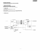
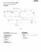
2. On-hook etetus detection circuit
The on-hook status detection circuit detects the Status of the hook
switch (RHS) of Built-in telephone, and the status of the hook of a
telephone externally connected.
l The status of on-hook switch (RHS) is determined from the logical
level of RHS signal.
RHS LOW : ON-HOOK
RHS HIGH : OFF-HOOK
l External telephone hook status detection circuit (m)
This circuit comprises the photo-coupler PCl, resistors R3 and R4,
Zener diodes ZDl and ZD2.
When an external telephone is connected and enters the on-hook
mode, the LED of photo-coupler PC1 emits light and the light receiv
ing element turns on. The status signal HS1 is input to the pin 64 of
(XFCR-MVP) (IC4: control PWB).
HSl LOW : EXT. TEL OFF-HOOK
HS1 HIGH : EXT. TEL ON-HOOK
3. Dial pulee generation circuit
The pulse dial generation circuit comprises the CML relay.
4. CML relay
The CML relay switches over connection to the matching transformer
Tl while the FAX or built-in telephone is being used.
5. Matching transformr
The matching transformer performs electrical insulation from the tel-
ephone line and impedance matching for transmitting the TEL/FAX
signal.
6. Hybrid circuit
The hybrid circuit performs 2-wire-to+wire conversion using the IC2
of operational amplifier, transmits the voice transmission signal to the
line, and feeds back the voice signal to the voice reception circuit as
the side tone.
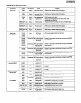
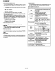
7. Signal selection
The following signals are used to control the transmission line of TEL/
FAX signal. For details, refer to the signal selector matrix table.
[Control signals from output port]
Sianal Name
CML
SP MUTE
TEL MUTE
RCVOL
The circuit is locatec
n the control PWB.)
VOLA
VOL B
VOL c
rhe circuit is locatec
I the control PWB.)
TXCONT
he circuit is lccatec
i the control PWB.)
GAIN-C
The circuit is located
I the control PWB.)
MPXA
-he circuit is located
1 the control PWB.)
BZCONT
he circuit is located
1 the control PWB.)
i
1
I
I
I
I
I
Descriotion
Line connectina relay and DP aeneratina rely
H: Line make
L: Line break
Sneaker tone mute control signal
H: Muting (Power down mode)
L: Muting cancel (Normal operation)
Handset receotion mute control siqnal
H: Muting
L: Muting cancel
Handset receiver volume control sianal
(Volol~ 1 Mirle IDTMF yding 1 H;h
SIDE KICK is two-stage switching.
Note: The DTMF sending listed above is DTMF signa
sending in the handset OFF-HOOK mode.
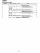
Speaker volume control signal
VRSELl VRSEL2 matrix
TXOUT mute sianal
H: Signal sending, when transmitting
L: During reception, transmission mute,
(during standby)
Receotion aain switching signal
L: When connected to line, 1: 1 gain
H: When not connected to line, HIGH gain
Transmission/transfer switching signal
H: When transmitting modem signal
(during standby)
L: When transferring
Speaker output signal switching
H: Buzzer signal output
L: When monitoring line signal
5-12