
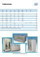
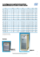
Technical data


10
©
FuG Elektronik GmbH, D-83135 Schechen, Am Eschengrund 11
http://www.fug-elektronik.de, E-Mail: info@fug-elektronik.de
V 0913
Function:
The mains voltage is first trans-
formed to the appropriate level.
On the secondary side of the
transformer is a thyristor con-
trolled rectifier stage (phase
cutting circuit). The rectified
voltage is smoothed by a LC -
filter.
Design:
Depending on voltage and
power the units are built as
single or double 19" cabinets
of various height. The side
covers are detachable, the
rear door is lockable.
All cabinets are equipped with
fork-lift-compatible plinths and
removable crane-eyes.
Single 19"- cabinets up to
38U are easily transportable
by fork-lift.
Cooling is carried out via con-
vection or built-in fans, with
the air being exhausted
(depending upon type) either
via the rear or the top.
Output:
Output isolation:
The output is floating. The
maximum operating voltage
with respect to earth: ±500V.
Either the positive or the
negative terminal may be
connected to earth.
Output terminals:
All output terminals are locat-
ed at the rear side of the
cabinet. For Output current
up to 300A feed though termi-
nals are used; for higher
currents the output is via
copper bars.
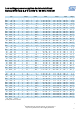
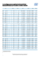
Technical Data:
Mains connection:
400V ±10% 47Hz to 53Hz;
three-phase
Ambient temperature:
0°C to +40°C
The following data applies for
voltage and current regulation,
and refers to the rated value
(unless otherwise stated):
(For explanations please refer
to Definitions and Terms on
page 54.)
Setting range:
from approx. 1% to 100%
Setting resolution:
±1 x 10
-4
Residual ripple (0 - 10MHz):
<1 x 10
-2
pp + 100mVpp
Recovery time:
<100ms to 500ms (depending
on type) for load variations of
±10%
Setting time at nominal load:
<100ms to 2sec (depending
on type) for changes of the
output voltage from 10% to
90% or 90% to 10%
Discharge time constant
for output without load:
approx. 5sec. to 60sec., de-
pending on type
Deviation:
For ±10% mains voltage vari-
ation:
<±1 x 10
-4
For no load / full load:
<±1 x 10
-3
Over 8 hours under constant
conditions:
<±3 x 10
-4
Within the temperature range:
<±3 x 10
-4
/K
Possible Options:
Analog programming (One of
the outputs on “0V” - poten-
tial; see also page 44)
Analog programming, floating
(see page 44)
Computer interfaces - IEEE
488, RS 232, RS 422, Profi-
bus DP, USB, LAN (more on
request) (see page 46)
Internal resistance setting and
regulation (see page 48)
Power regulation with display
(see page 48)
Roller blades for cabinet units
More options and special solu-
tions on request. Some options
may involve changes to the
description of the unit - espe-
cially concerning the mechani-
cal design.
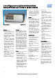
Low voltage power supplies thyristor regulated
Series NYN from 12,5 V to 350 V / 7 kW to 100 kW
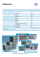
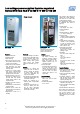
Design Example
NYN 70000 - 35
35V / 2000A
NYN 42000M - 84
84V / 500A
customer specific design with
current consumption unit
(Side covers removed)
Features:
Simple construction
Extremely robust
High efficiency
Short circuit proof and unlim-
ited operation with full current
in short circuit condition
Voltage and current regulation
with automatic and sharp
transition; control modes indi-
cated by LEDs
Voltage and current setting
with 10-turn potentiometers
with precision scale; the ad-
justing knob can be locked
Sense terminals for the com-
pensation of voltage drop on
the load lines. The nominal
voltage always refers to the
output terminals
Limitation of inrush current on
switching on
Suitable also for inductive and
capacitive loads
Interlock loop to monitor the
external load and internal loop
as a standard
Elapsed-hour meter as a
standard