INSTALLATION MANUAL SIMRAD CX34/44/54 NavStation 183-3450-102 06134.
About this manual The technical data, information and illustrations contained in this publication were to the best of our knowledge correct at the time of going to print. We reserve the right to change specifications, equipment, installation and maintenance instructions without notice as part of our policy of continuous development and improvement.
Precaution: Do not open the equipment, only authorized Simrad technicians are qualified to do so. If the glass in the screen breaks, be carefull not to cut yourself on the sharp edges of the glass pieces. There is high voltage present inside the scanner which may also be present even after power is turned off. ) The lifetime of the internal battery is minimum 5 years. If not exchanged before it goes flat, all data in the unit’s memory will be lost.
Installation Table of contents Installation instructions for the CX34/44/54 - series 1. 1.1 1.2 1.3 1.4 1.5 1.6 1.6.1 1.7 1.8 1.8.1 1.8.2 1.8.3 1.8.4 1.8.5 1.9 1.10 1.11 1.12 1.12.1 1.12.2 1.13 1.13.1 1.13.2 1.13.3 1.13.4 1.13.5 1.13.6 1.14 Installation instruction ..................................................................1-1 Installation notes ...........................................................................1-1 Installation of CX34 ......................................................
Table of contents Installation
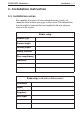
CX34/44/54 NavStation Installation 1 - 1 1. Installation instruction 1.1 Installation notes For a number of reasons, all user-related decisions, setups, etc. should be noted in these two pages as they occur. This information may be helpful if your unit has been updated with new software, reset or in for service.
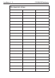
Installation 1 - 2 Other important settings: CX34/44/54 NavStation
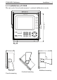
CX34/44/54 NavStation Installation 1 - 3 1.2 Installation of CX34 The unit can be flat or bracket mounted - overhead, bulkhead or console. 246 mm (9.7”) 220 mm (8.7”) 242 mm (9.5”) 220 mm (8.7”) SIMRAD 212 mm (8.3”) 33 (1.3”) 188 mm (7.4”) 112 mm (4.4”) 78 mm (3.1”) Console mounting. Overhead mounting. Bulkhead mounting.
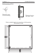
Installation 1 - 4 CX34/44/54 NavStation Flush mounting of CX34 Removable corner for flush mounting. Minimum clearance incl. cables: 15 cm. Refer to included template for instructions on flush mounting.
CX34/44/54 NavStation Installation 1 - 5 1.3 Installation of CX44 245 mm (9.6”) 220 mm (8.8”) The unit can be flat or bracket mounted - overhead, bulkhead or console. 343 mm (13.5”) 42 (1.7”) 365 mm (14.4”) 75 mm (3.0”) 165 mm (6.5”) 75 mm (3.0”) Console mounting. Overhead mounting. Bulkhead mounting.
Installation 1 - 6 CX34/44/54 NavStation Flush mounting of CX44 Removable corner for flush mounting. Minimum clearance incl. cables: 11 cm. 192 mm (7.6”) 202 mm (7.9”) 208 mm (8.2”) 220 mm (8.7”) Refer to included template for instructions on flush mounting. 337 mm (13.3”) 347 mm (13.7”) 353 mm (13.9”) 365 mm (14.
CX34/44/54 NavStation Installation 1 - 7 1.4 Installation of CX54 42 (1.7”) 343 mm (13.5”) 460 mm (18.1”) 95 mm (3.7”) 75 mm (3.0”) Console mounting. 195 mm (7.7”) Bulkhead mounting. 339.2 mm (13.4”) 330 mm (13”) The unit can be flat or bracket mounted - bulkhead or console. Overhead and bulkhead mounting is only possible if using a distance piece.
Installation 1 - 8 CX34/44/54 NavStation Flush mounting of CX54 Removable corner for flush mounting. Minimum clearance for cables: 13 cm. 297.9 mm (11.7”) 307.9 mm (12.1”) 318 mm (12.5”) 330 mm (13”) Refer to included template for instructions on flush mounting. 427.9 mm (16.8”) 437.9 mm (17.2”) 448 mm (17.6”) 460 mm (18.
CX34/44/54 NavStation Installation 1 - 9 1.5 Location for display unit Determine which place is the most suitable and convenient for navigation and general operation after considering the following conditions: - you can see the ship’s bow when you raise or lower your eyes from the display. - there is limited exposure to direct sunlight to avoid overheating - see environment temperature limits in 1.14 Specifications. - there is good ventilation and minimum vibration.
Installation 1 - 10 CX34/44/54 NavStation The NMEA1 interface from the main unit CX44/54 is transferred to the dual station via the connection cable and is available on the dual station’s NMEA2 receptacle. ) Refer to section 1.8 for details on pin numbers. O-ring 153-3002-023 The connection cable between the dual station and the main unit is a special pair-twisted cable of 15 meters, which consists of the following wires: 1.6.
CX34/44/54 NavStation Installation 1 - 11 1.7 Connection of Radar supply box RS4050 or RS4052 To run the radar scanners RB714/5/6/7/8A, an external power supply must be connected to the CX34/44/54. ) Be carefull to choose the correct supply box for the connected scanner. The RS4050 is for the 2kW and 4kW scanners. Ship’s mains 12 or 24 volt. Instructions and template for mounting, see Addendum no. 183-0700-003. Radar supply 4AF Dimensions: 125x222x81mm Radar motor 6A.3F Main 6A.
Installation 1 - 12 CX34/44/54 NavStation 1.8 Electrical connections Page 1-12 and 1-13 are for CX34.
CX34/44/54 NavStation Installation 1 - 13
Installation 1 - 14 CX34/44/54 NavStation Electrical connections continued Page 1-14 and 1-15 are for CX44/54.
CX34/44/54 NavStation Installation 1 - 15
Installation 1 - 16 CX34/44/54 NavStation 1.8.1 Power supply connections - refer also to section 1.7 The internal voltage regulator will allow the CX34/44/54 to operate normally within the power supply voltage range from 10 to 32 V DC. The CX34/44/54 is connected to external power (battery or radar supply box) by means of the supplied power cable, which is approximately 2 meters long and is not extendable.
CX34/44/54 NavStation Installation 1 - 17 CX44/54: Transducer connections: Internal connections Transceiver Transceiver 1 2 50/200kHz 38/200kHz ECHO1 ECHO2 Combi transducer 38 and 200, or 50 and 200kHz Single frequency 50 or 200kHz Single frequency 38 or 200kHz Two frequency 50/200kHz ! Warning! Transducers containing speed log sensor e.g. Airmar B744V must never be connected to the port “ECHO2”.
Installation 1 - 18 CX34/44/54 NavStation 1.8.4 Interface connection The 34, 44 and 54 series feature three possibilities for interconnection and data sharing: 1. SimNet, which is recommended for control and data sharing between Simrad SimNet products. 2. NMEA2000, SimNet products will interface and share data with NMEA2000 based products. 3. NMEA0183, which has been the common standard for marine electronics.
CX34/44/54 NavStation Installation 1 - 19 SimNet power and termination The following simple rules should be observed when installing SimNet: • SimNet must be powered with 12 VDC and connected to the battery via circuit breaker and 5 amp fuse. • Do not connect the SimNet power cable to the same terminals as the Autopilot Computer, Radar, thruster or other high current products.
Installation 1 - 20 CX34/44/54 NavStation SimNet / NMEA2000 network, medium system CX33 * CX44 12V supply Tee Joiner AT44 Active Tee * The supply cable and wind transducer have a built-in terminator. 1.8.5 PC up/download via NMEA connection A PC can be connected to CX34 via the NMEA port, or to CX44/54 via the NMEA2 port, to enable exchange of waypoint and route data.
CX34/44/54 NavStation Installation 1 - 21 1.9 Installation of GPS / DGPS antenna The antenna must be placed in a position where tall constructions, steel wires, masts, etc. do not obstruct the view to the satellites. Do not, however, mount the antenna in the top of a mast or tower, as this may degrade the COG and SOG readings, especially if DGPS is used. Do not place the antenna close to sources of electrical inteference, such as radar, satcom, etc.
Installation 1 - 22 CX34/44/54 NavStation 1.10 Optional connections SIMRAD -Compass -WR20 RemoteCommander -Dual Station DS34/44/54-CX -Performance Instruments -Differential Beacon Receiver -Water speed and temperature sensor -Autopilot -Yeoman digitizer -PC - WPs & routes up/download -Other equipment via SimNet, NMEA0183, or NMEA2000. 1.
CX34/44/54 NavStation Installation 1 - 23 1.12 Basic transducer and cable information The installation should be carefully planned in advance, keeping in mind the standard cable length of 10 meters (32 feet) which is connected to the transducer. In the event where the standard cable is not long enough, up to an additional 10 meters (32 feet) may be connected without a noticeable reduction of the performance. The cable must be of the same type as the standard cable.
Installation 1 - 24 CX34/44/54 NavStation 1.12.1 Transducers Simrad Combi-transducers C50/200 or C38/200 For optimum performance of the CX44/54 echosounder function, the Simrad combi transducers C38/200 and C50/200 are recommended. These transducers also include a water temperature sensor. A variety of alternative mediumrange transducers is available for vessels mainly operating in shallow waters and/or where the size of the transducer is critical. 124.
CX34/44/54 NavStation Airmar P319 Installation 1 - 25 Thru-hull mount Frequency: 50/200 kHz Beamwidth: 45° / 15° Cable length: 10m (32’) Depth information. Reference no. 179-0401-002 (P319) Housing: Reinforced plastic Recommended for fiberglass and metal hulls. Do not use in wooden hulls! Reference no. 179-0401-003 (B117) Housing: Bronze Recommended for fiberglass and wooden hulls.
Installation 1 - 26 CX34/44/54 NavStation Airmar SS505 Thru-hul stem mount Accomodates hull thickness: Min. no fairing 6 mm (1/4”), Max. with fairing 83 mm (3 1/4”) Frequency: 50/200 kHz Beamwidth: 45° / 15° Cable length: 10m (32’) Depth information. Ref.no. 179-0401-004 (B45) Housing: Bronze Recommended for fiberglass or wooden hulls only. Ref.no. 179-0401-008 (SS505) Housing: Stainless steel Recommended for any hull material. Ref.no.
CX34/44/54 NavStation Installation 1 - 27 Airmar B744V Thru-hull triducer Frequency: 50/200 kHz Beamwidth: 45° / 15° Cable length: 10m (32’) Speed, temperature + depth information. Ref.no. 179-0401-009 (B744V) Housing: Bronze Recommended for fiberglass and wooden hulls. ) Do not connect to CX44/54’s ECHO2 port. 1.12.
Installation 1 - 28 CX34/44/54 NavStation can be great variation in the amount of air bubbles which are carried beneath the hull. These bubbles tend to be carried close to the hull as they pass aft. For this reason, it is desirable for the transducer to be mounted on a fairing block which holds the transducer away from the hull and which directs the flow of aerated water around the sides of the transducer rather than over the face of the transducer.
CX34/44/54-series Installation 1-29 1.13 Installation of scanner This illustration is a typical radar system: Radar scanner Display unit GPS antenna Compass 12/24 Volt supply 12 Volt supply AT44 SimNet How to determine the site of installation A radar’s target detection capacity varies greatly depending on the fitted position of the scanner. An ideal fitting position is a location high above the ship’s keel line where there is no obstacle all around the scanner.
Installation 1-30 CX34/44/54-series 1.13.1 Shifting away from obstacles Shifting from keel line: By shifting the scanner position from the keel line to the starboard side of the ship, it is possible to move shadow zones to the port side which makes it possible to keep a clear vision in the bow direction. The distance to be shifted can be obtained by calculation depending on the distance from the scanner to obstacles using the following equation: Ls=0.4R+D/2 [m] (when R<15 m) Ls=0.
CX34/44/54-series Installation 1-31 1.13.2 Mounting of scanner Deciding the place of installation, a minimum distance must be considered to the master compass (2 meters) and steering compass (1.4 meters). If a mount base like the one shown below is available, it may be easier to install the scanner. If not available, you may install the scanner directly to the roof, etc. In this case, pay attention to the water drain tube located at the bottom of the scanner unit during installation.
Installation 1-32 CX34/44/54-series DX45 Radome scanner 465 mm (18.3”) • 46.5 cm radome • 4 kW • Range up to 28 nm • Rotation speed 20-50 rpm • Beamwidth: Horizontal 5.6° Vertical 30° 261 mm (10.3”) Forward The four bolts included with your radar equipment will suffice for mount base thickness of 9 to 14 mm (0.35 to 0.55 in.). If the mount base is thicker or thinner than this, prepare bolts as listed on page 1-31. Use silicone to secure the bolts.
CX34/44/54-series Installation 1-33 DX60 Radome scanner • 61.5 cm radome • 4 kW • Range up to 36 nm • Rotation speed 20-50 rpm • Beamwidth: Horizontal 3.8° Vertical 30° 615 mm (24.2”) 261 mm (10.3”) Pads for support of radome scanner DX60: If the DX60 is to be mounted on a flat surface, the four pads (included) for support are to be placed according to this illustration. To fit the pads, peel off the paper and place them with the adhesive part onto the radome bottom.
Installation 1-34 CX34/44/54-series RB714A Radome scanner 448 mm (17.9”) • 45 cm radome • 2 kW • Range up to 24 nm • Rotation speed 24 rpm • Beamwidth: Horizontal 5.9° Vertical 25° 220 mm (8.8”) Chassis Radome (bottom) Mounting base Washer Spring washer Included M10 Hexagonal bolt Fix four bolts DRILLING TEMPLATE Forward 140mm (5.51 in.) 12φ × 5 (0.47 in.) 60 (2.36 in.) 140 Center (5.51 in.) 30 (1.18 in.
CX34/44/54-series Installation 1-35 RB715A Radome scanner • 65 cm radome • 4 kW • Range up to 36 nm • Rotation speed 24 or 48 rpm • Beamwidth: Horizontal 3.9° Vertical 25° 660 mm (26.4”) 255 mm (10.2”) Chassis Radome (bottom) Mounting base Washer Spring washer Fix four bolts Included M10 Hexagonal bolt DRILLING TEMPLATE The bolts included with your radar equipment will suffice for mount base thickness of 9 to 14 mm (0.35 to 0.55 in.).
Installation 1-36 CX34/44/54-series RB716A Open scanner • 3 or 4ft Open array • 4 kW • Range up to 48 nm • Rotation speed 24 or 48 (24V) rpm • Beamwidth: Horizontal 2.5°, 1.8° Vertical 22° 4’ 1346mm (53.8”) 3’ 1034mm (41.4”) 330mm (13.2”) 450mm (18”) RB717A Open scanner RB718A Open scanner • 4 or 6 ft Open array • 6 kW • Range up to 72 nm • Rotation speed (24V) 24 or 48 rpm • Beamwidth: Horizontal 1.8°, 1.
CX34/44/54-series Installation 1-37 Drilling template for RB716A, RB717A, RB718A. Rotation Radius R550 (3 ft. ant.) R700 (4 ft. ant.) R985 (6 ft. ant.) Front The bolts included with your radar equipment will suffice for mount base thickness of 9 to 14 mm (0.35 to 0.55 in.). If the mount base is thicker or thinner than this, prepare bolts as listed on page 1-31. Silicone should be applied to secure the bolts. Do not use locking putty, as it may damage the radome.
Installation 1-38 CX34/44/54-series Interconnecting cable (DX45 + DX60) 1. Run the cable and fasten it at intervals of about 40 cm. 2. Remove the upper part of the radome from the scanner (loosen 4 screws with incl. Allen key). Avoid bumping it against the antenna by lifting it vertically. 3. Remove the shield cover located on the astern side (8 screws) - use a T20 screwdriver. 4. Pass the cable up through the opening and place the cable screen into the groove (Fig.
CX34/44/54-series Installation 1-39 Interconnecting cable (DX45 + DX60) - continued Pull cord White (coax) Green (shield) Blue Yellow NC White Brown Green Red Pull cord 1 Fig.1 Pull cord Blue Green Violet Yellow Orange Red Pull cord 1 Fig.2 Logo seal on side wall Fig.3 Ship’s heading Cable inlet Tighten the four screws to 1.
Installation 1-40 CX34/44/54-series Interconnecting cable (RB714A + RB715A) 1. Run the cable, and fasten it at intervals of about 40 cm. 2. Remove the upper part of the radome from the scanner (loosen 4 screws). Avoid bumping it against the antenna by lifting it vertically. 3. Remove the tape securing the antenna. 4. Remove the shield cover located on the astern side (4 screws). 5.
CX34/44/54-series Installation 1-41 Fitting interconnection cable (RB714A): Antenna Stern side Shield cover Cable shield Radome (bottom) Fixing plate Fix connector on X1 Rubber ring Interconnection cable Inner shield PCB X1 (Connect here) Radome (bottom)
Installation 1-42 CX34/44/54-series Fitting interconnection cable (RB715A): Antenna Stern side Shield cover Cable shield Fixing plate Radome (bottom) Rubber ring Fix connector on PCB X11, X12 Interconnection cable Inner shield PCB X11 (Connect here) Radome (bottom) X12 (Connect here)
CX34/44/54-series Installation 1-43 Interconnecting cable (Open Scanner) 1. Run the cable, and fasten it at intervals of about 40 cm. 2. Use a T-wrench to remove the back covers of the scanner unit. 3. Remove the two bolts securing the transceiver and pull out the transceiver after removing two connectors: to Motor (X1) and to Heading switch (X2). 4. Remove the four bolts securing the fixing plate at the cable entrance. 5. Remove the metal fixing plate, rubber seal and washer that secures the cable. 6.
Installation 1-44 CX34/44/54-series Fitting interconnection cable (Open scanner): TR unit fixing bolts Remove connector Fixing bolt Clumper Fixing plate Interconnection cable X11 X12 Fixing bolt Cable shield terminal 5 10 mm Washer Fixing plate Scanner unit Interconnection cable Rubber Cable inlet
CX34/44/54-series Installation 1-45 1.13.4 Connector’s pin numbers and wire colors The connecting cable is supplied with the radar scanner. The 18-pin round connector is connected to the main unit’s receptacle marked RADAR: 2 1 4 3 7 8 12 16 5 6 9 10 14 13 17 11 (seen from solder side) 15 18 – refer to section 1.8 for details on pin numbers.
Installation 1-46 CX34/44/54-series Connector for the RB714A Radar scanner Connector for the RB715A Radar scanner
CX34/44/54-series Installation 1-47 Connector for the Open Scanners (RB716A, RB717A, and RB718A)
Installation 1-48 CX34/44/54-series 1.13.5 Grounding wire Connect a grounding wire from one of the bolts on the scanner base, as shown below. The crimp terminal and grounding wire are installer-supplied. Chassis Radome Radome (bottom) Mount base To ship’s hull Crimp terminal Grounding wire Open scanner Terminal (accessory) Ground wire 1.13.
CX34/44/54-series Installation 1-49 1.14 Specifications of the CX34, 44 & 54 General data Power supply: 12 and 24 V DC (10-32 V DC max) 20-70 watt (+ Radar supply box - see next page) Power cable: 2 m, 4 pin female connector, (153-5000-007), inclusive: - power fuse T6.3A slow (5x20mm) - fuse for DX radar scanners F8.0A fast (5x20mm) CSD: Compass Safe Distance: 650mm (25.6”) Dimensions: CX34: H:220 mm (8.7”) L:220 mm (8.7”) D:112 mm (4.5”) CX44: H:220 mm (8.7”) L:365 mm (14.
Installation 1-50 CX34/44/54-series Radar supply box RS4050 to run radar scanners RB714/5/6A Addendum: 183-0700-003 Dimensions: H:125 mm, L:222 mm, D:81 mm Power supply: 12 and 24 V DC (10-32 V DC max) Fuses: Radar supply fuse 4A F Main fuse 6A.3F High voltage fuse 160 mAF Radar motor fuse 6A.3F Radar supply box RS4052 to run radar scanners RB717/8A Addendum: 183-0700-004 Dimensions: H:161.9 mm, L:263 mm, D:91 mm Power supply: 24 V DC (18-32 V DC max) Fuses: Radar supply fuse 10 AT Main fuse 6A.
CX34/44/54-series Installation 1-51 Chartplotter section Chart system: C-MAP MAX or NT+ Presentation: Dual chart - two charts in individual scales and detail levels Internal memory: Dynamic storage with combinations of/or totals up to: 35,000 marks/waypoints 10,000 waypoints with name (25 characters) 50,000 trackpoints 50,000 line sections 1,000 routes Radar section Display modes: Head Up, North Up, True Motion, Dual Range. Range scale: 0.125–48 nm in 11 steps or multi range. Min.
Installation 1-52 CX34/44/54-series Antenna: Slotted waveguide array, horizontal polarization, rotation rate 20-50 rpm. - beam width: DX45 = 5.6° horizontal, 30° vertical. DX60 = 3.8° horizontal, 30° vertical. Housing: Casted aluminum and ASA. Cables: 10m 153.3003.100 15m 153.3003.150 20m 153.3003.200 30m 153.3003.300 40m 153.3003.
CX34/44/54-series Installation 1-53 Echosounder section (CX34) Frequencies: 50 or 200 kHz, selectable Transmit power: Variable up to 600 watt RMS (4,800 W PP) Impedance: 175 / 425 ohm Display ranges: 5 to 1000 m (50kHz) or 5 to 400 m (200kHz), manual and auto mode.
Installation 1-54 CX34/44/54-series Alarms: Zoom mode: Fish, max. and min. depth Shift, bottom and VRM expansion, 3 to 50 meter, feet or fathom Event marker: At current ping and depth memory Picture speed: True distance or time, high, medium, low, and freeze Noise filter: User selectable on/off Echo presentation: A-scope and white line discrimination Temperature: Sensor or NMEA Speed: Sensor or NMEA 50/200kHz medium-range transducers (Airmar Des.
CX34/44/54-series Installation 1-55 SimNet cables and accessories (not included) SimNet cable 0.3 m (1’), (24005829) SimNet cable 2 m (6.6’), (24005837) SimNet cable 5 m (16.6’), (24005845) SimNet cable 10 m (33’), (24005852) SimNet Tee Joiner, 3 sockets (24005860) SimNet Multi Joiner, 7 sockets (24006298) SimNet cable gland (24005878) SimNet protection plug (24005886) SimNet termination plug (24005894) 2 m (6.6’) SimNet power incl. termination (24005902) 2 m (6.6’) SimNet power excl.
Installation 1-56 CX34/44/54-series