
Parts List/Tune Up Info

FCC ID: APYHRO00298
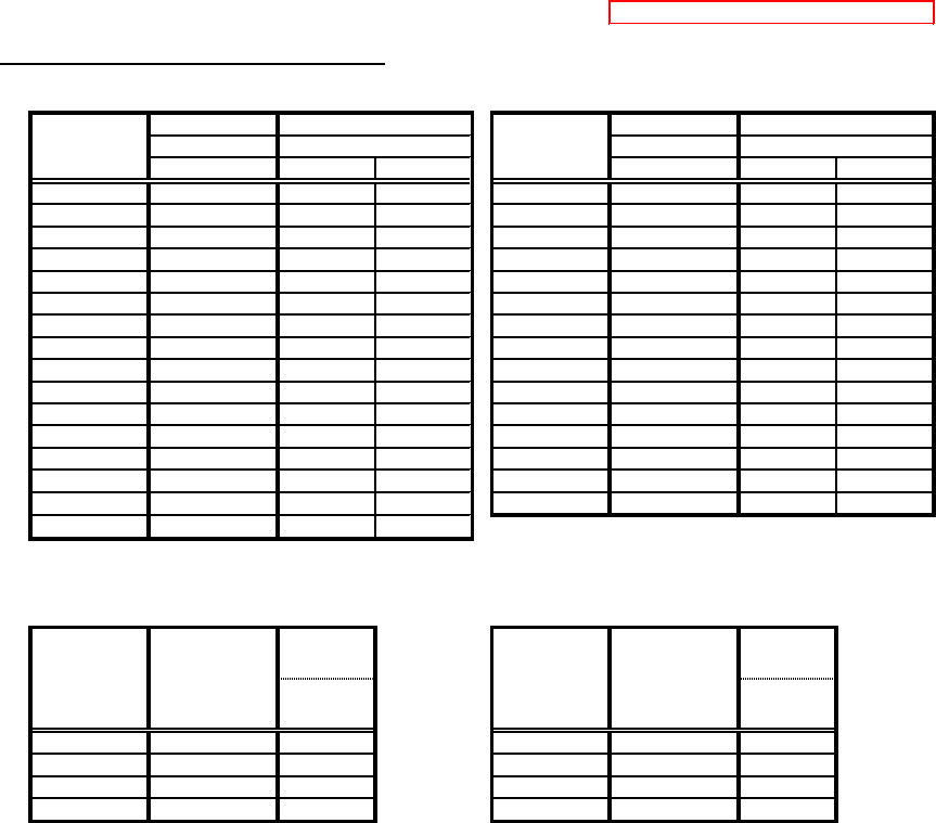
TUNE UP PROCEDURE For GSM850/PCS1900
PCS1900 Output Power All channels are common. GSM850 Output Power All channels are common.
Target [dBm] Target [dBm]
Burst Ave. Burst Ave.
Typical Min. Max. Typical Min. Max.
0 29.5 28.2 30.5 5 32.5 31.2 33.5
1
27.5
25.5 29.5 6
30.5
28.5 32.5
2
25.5
23.5 27.5 7
28.5
26.5 30.5
3
23.5
21.5 25.5 8
26.5
24.5 28.5
4
21.5
19.5 23.5 9
24.5
22.5 26.5
5 19.5 17.5 21.5 10 22.5 20.5 24.5
6 17.5 15.5 19.5 11 20.5 18.5 22.5
7 15.5 13.5 17.5 12 18.5 16.5 20.5
8 13.5 11.5 15.5 13 16.5 14.5 18.5
9 11.5 8.5 14.5 14 14.5 12.5 16.5
10 9.5 6.5 12.5 15 12.5 10.5 14.5
11 7.5 4.5 10.5 16 10.5 6.5 14.5
12 5.5 2.5 8.5 17 8.5 4.5 12.5
13 3.5 0.5 6.5 18 6.5 2.5 10.5
14 1.5 -2.5 5.5 19 4.5 0.5 8.5
15 0.0 -4.0 4.0
The Maximum Output Power in a multislot configuration The Maximum Output Power in a multislot configuration
(GPRS MultiSlot Class = 12 , (GPRS MultiSlot Class = 12 ,
GMSK_MULTISLOT_POWER_PROFILE = 0 ) GMSK_MULTISLOT_POWER_PROFILE = 0 )
Spec.
[dBm]
Spec.
[dBm]
Burst Ave.
Max.
Burst Ave.
Max.
1 29.5 30.5 1 32.5 33.5
2 27.2 28.2 2 30.2 31.2
3 25.3 26.3 3 28.3 29.3
4 24.3 25.3 4 27.3 28.3
The difference between the transmitter output power at two adjacent power control levels,
measured at the same channnel, is not less than 0,5 dB and not be more than 3,5 dB.
If one or both of the adjacent output power levels are reduced according to
GMSK_MULTISLOT_POWER_PROFILE 0 and the number of timeslots, the difference between the
transmitter output power at two adjacent power control levels, measured at the same frequency, shall not be less
than -1dB and not be more than 3.5 dB.
PCL
The Number
of Timeslots
in uplink
assignment
Max. Limit of
Typ. Output
Power [dBm]
Burst Ave.
Burst Average
PCL
Burst Average
Spec. [dBm]
Confidential
Spec. [dBm]
The Number
of Timeslots
in uplink
assignment
Max. Limit of
Typ. Output
Power [dBm]
Burst Ave.