TECHNICAL MANUAL CXE LOW TEMPERATURE SPLIT SYSTEMS 55908022-02
INDEX CONTENTS PAGE PART NUMBERS, UNIT COMBINATIONS, OPTIONS, DIMENSIONS & WEIGHTS 3 PERFORMANCE DATA 3 AIR FLOWS, SOUND POWER AND SOUND PRESSURE LEVELS 4 ELECTRICAL DATA 5 CXE DIMENSIONS 6 INSTALLATION: CONTENTS & PIPEWORK 7 ELECTRICAL: FUSES & WIRING DIAGRAMS 7-8 INSTALLATION: DIMENSIONS 8-9 PIPEWORK 9 - 10 CKC ELECTRICAL 11 REFRIGERANT 12 COMPONENT IDENTIFICATION CXE UNITS 13 CKC UNITS 14 GENERAL 1.
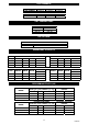
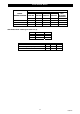
PART NUMBERS MODEL PART NUMBER CXE 40 55900016 CXE 50 55900015 CXE 70 55900014 MODEL PART NUMBER CKC 20 1ph 55023720 CKC 40 1ph 55023741 CKC 60 1ph 55023740 UNIT COMBINATIONS INDOOR UNIT CXE 40 CXE 50 CXE 70 OUTDOOR UNIT CKC 20 CKC 40 CKC 60 CXE OPTIONS OPTIONAL KITS DESCRIPTION 3kW heater PART NUMBER 55900715 DIMENSIONS & WEIGHTS MODEL CX(E) 40 50 70 HEIGHT 483 483 483 UNPACKED WIDTH DEPTH 845 320 845 320 845 320 CKC HEIGHT WIDTH DEPTH 20 40 60 620 620 720 900 900 1000 310 310 310 W
AIR FLOWS MODEL CXE 40 CXE 50 CXE 70 m³/s 0.61 0.66 0.58 MODEL CKC 20 CKC 40 CKC 60 m³/s 0.81 0.72 0.78 SOUND POWER AND SOUND PRESSURE LEVELS INDOOR UNIT MAXIMUM SPEED CXE 40 CXE 50 CXE 70 125 69.1 71.7 70.1 SOUND POWER LEVELS Frequency Hz 250 500 1K 2K 67.7 67.6 65.6 62.2 69.2 69.1 67.1 63.2 68.2 68.6 66.1 63.2 4K 56.0 58.5 57.5 SOUND PRESSURE LEVELS NC dB(A) 55 48 56 50 56 49 Sound Power Levels were obtained in full accordance with the direct method of BS EN ISO3174:2000.
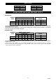
ELECTRICAL DATA MODEL INDOOR/OUTDOOR CXE 40 + CKC 20 CXE 50 + CKC 40 CXE 70 + CKC 60 1 PH 230V 50Hz FULL LOADS AMPS COOLING HEATING COOLING HEATING kW kW AMPS AMPS SYSTEM MAX. STARTING CURRENT AMPS 1.3 2.1 2.4 3.1 3.1 3.1 7.15 10.2 9.8 12.8 13.8 13.8 28 50 61 INPUT POWER UNIT ELECTRICAL LOADS [230V 50Hz 1Ph (A) MODEL CXE 40 CXE 50 CXE 70 FAN MOTOR 0.8 0.8 0.8 CKC Fan motor R407C compressor (1 Ph) nominal FLA Crankcase heater HEATER 13.0 13.0 13.0 20 0.6 6.9 0.25 40 0.6 10.2 0.
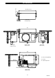
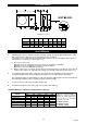
888 (Fixing centers) 20 124 (Fixing centers) CXE DIMENSIONS 17.5 39 TOP VIEW (Ceiling Mounted) 888 39 17.5 124 96 60 320 120 MIN. 120 96 SIDE VIEW (Ceiling mounted) FRONT VIEW SIDE VIEW (Wall mounted) (Wall mounted) 845 X X MIN. 500 FOR SIDE ACCESS Z1 75 Z2 Z 1 = Suction Z 2 = Liquid / Expansion 215 140 483 36 X = Interconnecting Wiring 70 35 65 TYP. CONDENSATE DRAIN 22mm OD 422.
PARTS DESCRIPTION Envelope containing operating instructions and Declaration of Conformity 0.037" restrictor (CXE 40 only) 0.051" restrictor (CXE 50 only) 0.057" restrictor (CXE 70 only) Mounting brackets Drain Stub/Nut/Gasket Drain stub adaptor Screw M5 Washer nylon Washer M5 shakeproof CONTENTS QTY Reducing flare nut 1/2” – 3/8” ACTION 1 Pass to the end user. 1 1 1 2 1 1 6 6 6 Use with CKC 20 outdoor unit. Use with CKC 40 outdoor unit. Use with CKC 60 outdoor unit. Use to hang unit.
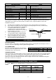
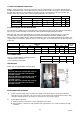
WIRING DIAGRAM CKC INSTALLATION MOUNTING Whether floor or wall mounted, it is essential that the mounting surface is capable of supporting the unit weight. Leave space around the unit for air circulation and access for installation and maintenance. 100 min 100 min 600 min 1500 min air off Dimensions in mm.
CKC DIMENSIONS (Dimensions in mm.) MODEL A B C D E F G H CKC 20 CKC 40 CKC 60 900 900 1000 300 300 300 560 560 660 525 525 570 185 185 213 60 60 60 333 333 333 308 308 308 CKC PIPEWORK 1. Individual pipe runs to a maximum of 20m, including 7.5m lift, are permissible with liquid lines, 80m with expansion lines, provided good refrigeration practice is followed. Performance is based on 7.5m pipe runs.
A. USING SUCTION AND LIQUID LINES: With the expansion device connected to the indoor unit, the equivalent pipe run should be 20m maximum, including a maximum lift of 7.5m. Fully insulate the suction line. Ensure the suction pipe is insulated well over the drain tray at the indoor unit. Liquid lines should be routed to avoid hot areas. This prevents flash gas forming, which may result in erratic control of liquid refrigerant to the evaporator.
c. Place the flare nuts over the incoming pipework and flare the pipe ends. The use of a little refrigeration oil on the flaring tool will help. d. Connect the pipework between the units. Do not leave pipe ends, valves etc. open to the atmosphere. R407C is very hygroscopic, and will absorb damaging levels of moisture if left open. Always use two spanners when tightening the flare nuts to avoid twisting the pipes. Use a small amount of refrigerant oil on the mating surfaces. e.
CKC REFRIGERANT ADDING REFRIGERANT 1. The unit is fitted with head pressure control; before charging, isolate the outdoor unit and transfer the motor wire on the head pressure control from terminal 4 to terminal 1. (Don't forget to transfer it back after charging). 1 2 3 4 444 ☺ BLUE MOTOR WIRE ☺ 4 HPC 2. If a manual HP cut-out is fitted, ensure that the reset button is depressed. 3. A 3 minute delay occurs between successive compressor operations. 4.
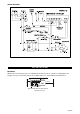
CXE INDOOR UNIT COMPONENT IDENTIFICATION 1 2 3 14 4 15 5 13 10 11 9 Grille Fan / motor Case Wall / ceiling mounting brackets Heater bracket Coil assembly Thermostat bulb & bracket Restrictor assembly / extended pipe (option) 9 10 11 12 13 14 15 De-ice stat Heater assembly (option) Drain stub adaptor Drain tray Side access panel Electrics box door Controller INSIDE VIEW OF ELECTRICS BOX N Mains Cable Entry Point L MAINS IN E L CU OUT E CU SPARE 1 2 3 4 5 6 7 8 7 8 12 N 4 6 Cap
CKC OUTDOOR UNIT COMPONENT IDENTIFICATION 1 2 3 4 5 6 7 8 9 10 11 12 13 14 15 16 17 LID CONTACTOR OVERLOAD HEAT EXCHANGER COIL REAR ACCESS PANEL MAINS TERMINAL COVER FAN CAPACITOR BULKHEAD PANEL HP SWITCH (MANUAL, OPTION) SERVICE VALVE (LIQUID) SERVICE VALVE (SUCTION) VALVE PANEL BASE MOUNTING FOOT LP SWITCH COMPRESSOR HANDLE 18 19 20 21 22 23 24 25 26 27 28 29 30 31 32 33 FRONT ACCESS FAN GUARD FASCIA PANEL CORNER PANEL SUPPORT BRACKET FAN / MOTOR ASSEMBLY END CLAMP TERMINAL FUSE FUSE TERMINAL TERMINAL