
User`s manual
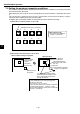


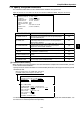
Table Of Contents
- Safety Precautions
- Table of contents
- Chapter 1: Outline
- 1-1 Features
- 1-2 Controller
- 1-3 Measurement program
- [1] Positional deviation measurement
- [2] Degree of match inspection
- [3] Lead inspection
- [4] BGA/CSP inspection (IV-S32M/S33M)
- [5] Area measurement by binary conversion
- [6] Object counting by binary conversion
- [7] Object identification by binary conversion
- [8] Point measurements
- [9] Distance and angle measurement
- [10] Multiple position measurement (IV-S33M)
- [11] Multiple degree of match inspection (IV-S33M)
- Chapter 2 : Precautions for Use
- Chapter 3 : System Configuration
- Chapter 4 : Part Names and Functions
- Chapter 5 : Connection and Installation Methods
- Chapter 6 : Setting and Operating Outlines
- Chapter 7 : Simplified Menu Operation
- 7-1 Operation screen
- 7-2 Image display
- 7-3 Setting functions that are different with each controller
- 7-4 Setting procedures
- 7-5 Setting the operation conditions
- 7-6 Setting object types
- 7-7 Setting the shutter speed
- 7-8 Setting the positioning conditions
- 7-9 Setting the existence inspection conditions
- 7-10 Measurement triggering
- 7-11 Saving data
- 7-12 Specify the system conditions
- Chapter 8 : Specifications
- Chapter 9 : Operation Examples
- Glossary
- Appendix
- Alphabetical Index

7-26
Simplified Menu Operation
7
(3) Triggered by a message on the general-purpose serial communication port
In this method, the IV-S30 and a personal computer communicate with each other using commands
and responses.
- Specify the communication setting parameters by referring to the "2 COMM. SET" item on the
[SYSTEM COND] menu. -See page 7-27
- For details about the communication commands, see the IV-S30 User’s Manual (Function and
Operation).
[2] Result output
The IV-S30 has three methods for outputting results, as shown below.
1 Output on the output terminals (Y0, Y1)
2 Output over the general-purpose serial communication port
3 Output using a programmable controller computer link
(1) Output on the output terminals
The IV-S30 outputs the measured result to the output terminal.
Y0: Final output result
This will be ON when the results of all the items are OK. (This is equivalent to the auxiliary relay
C112.)
Y1: Measurement execution error
This will be ON when a measurement processing error occurs. (This is equivalent to the
auxiliary relay C118.)
For details about the auxiliary relays C112 and C118, see the IV-S30 User’s manual (Function and
Operation).
(2) Output over the general-purpose serial communication port
With this method, the IV-S30 and a personal computer communicate with each other using
commands and responses.
- Specify the serial port parameters in the items "1SERIAL OUTPUT" and "2COMM. SET" on the
[SYSTEM COND] menu. -See page 7-27.
- For details about the communication commands, see the IV-S30 User’s Manual (Function and
Operation).
(3) Output using a programmable controller computer link
With this method, the IV-S30 and a programmable controller communicate with each other using the
computer link.
- Specify the computer link setting parameters in the items "1SERIAL OUTPUT," "2COMM. SET"
and "3COMPUTER LINK" on the [SYSTEM COND] menu. -See pages 7-27 and 7-28.
- For details about the computer link, see the IV-S30 User’s Manual (Function and Operation).
7-11 Saving data
All the data entered on the condition setting menus, such as the measurement conditions and evaluation
conditions, are saved in the IV-S30 flash memory.
ËË
ËË
Ë Operating procedure
1. On the [MAIN OPS MENU], move the cursor to "SAVE" using the left and right keys, and press
the SET key.
- The following message will be displayed on the upper part of the screen.
DATA SAVE? (Do you want to save the data?) (YES=[SET]/NO=[ESC])
2. Press the SET key.
- The IV-S30 will start saving the data and the progress will be displayed on the bottom of the
screen.
When the data has been saved in the IV-S30 flash memory, the display will change from
"SAVING" to "COMPLETE SAVE."
REFERENCE IMG
SYSTEM I/O
OBJECT TYPE COND
■■
■
■■■■■■■■■■■□□□□□
SAVING