
User`s manual


Table Of Contents
- Safety Precautions
- Table of contents
- Chapter 1: Outline
- 1-1 Features
- 1-2 Controller
- 1-3 Measurement program
- [1] Positional deviation measurement
- [2] Degree of match inspection
- [3] Lead inspection
- [4] BGA/CSP inspection (IV-S32M/S33M)
- [5] Area measurement by binary conversion
- [6] Object counting by binary conversion
- [7] Object identification by binary conversion
- [8] Point measurements
- [9] Distance and angle measurement
- [10] Multiple position measurement (IV-S33M)
- [11] Multiple degree of match inspection (IV-S33M)
- Chapter 2 : Precautions for Use
- Chapter 3 : System Configuration
- Chapter 4 : Part Names and Functions
- Chapter 5 : Connection and Installation Methods
- Chapter 6 : Setting and Operating Outlines
- Chapter 7 : Simplified Menu Operation
- 7-1 Operation screen
- 7-2 Image display
- 7-3 Setting functions that are different with each controller
- 7-4 Setting procedures
- 7-5 Setting the operation conditions
- 7-6 Setting object types
- 7-7 Setting the shutter speed
- 7-8 Setting the positioning conditions
- 7-9 Setting the existence inspection conditions
- 7-10 Measurement triggering
- 7-11 Saving data
- 7-12 Specify the system conditions
- Chapter 8 : Specifications
- Chapter 9 : Operation Examples
- Glossary
- Appendix
- Alphabetical Index
9-1
9
Operation Examples (Simplified menu: Positioning measurement)
metI egaP
1-9
unemdeifilpmiS
]1[tnemerusaemgninoitisoP5-9ot2-9
]2[noitcepsniecnetsixE9-9ot6-9
2-9
unemdradnatS
]1[noisrevnocyranibybtnemerusaemaerA41-9ot01-9
]2[tnemerusemnoitaivedlanoitisoP12-9ot51-9
IV-S3*M
OUTPUT
INPUT
POWER
Y7Y0 Y1 Y2 Y3 Y4 Y5 Y6
COM
COM
+24V
X7X0 X1 X2 X3 X4 X5 X6
READY
0V
VIDEO
CAMERA1
CAMERA2
USB
RS232C/RS422
REMOTE
Power supply (24 VDC)
Monitor
Camera 1
Remote key pad
Controller
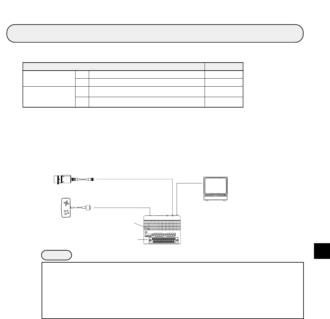
Chapter 9: Operation Examples
This chapter explains how to operate each measurement program. Be sure you understand the general
operation procedures described in this chapter.
ËË
ËË
Ë Preparation for operation
Before turning ON the power, connect the IV-S30 controller, the camera, monitor, remote key pad
and power supply (24 VDC). Connect the camera to the camera 1 connector (CAMERA 1) on the
IV-S30 controller.
See Chapter 5 "Installation Conditions and Method" for connecting procedures.
Notes
- Sections 9-1 and 9-2 give the instructions for making each measurement, starting from the
initial conditions of the machine. To follow the instructions, first initialize all the machine's
conditions and then start the procedures. For details about performing a complete
initialization, see the respective pages, described below.
- Simplified menus - Page 7-29
- Standard menus - "Total initialization" in the IV-S30 user’s manual (Function and
Operation)