
User`s manual

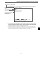


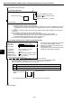


Table Of Contents
- Safety Precautions
- Table of contents
- Chapter 1: Outline
- 1-1 Features
- 1-2 Controller
- 1-3 Measurement program
- [1] Positional deviation measurement
- [2] Degree of match inspection
- [3] Lead inspection
- [4] BGA/CSP inspection (IV-S32M/S33M)
- [5] Area measurement by binary conversion
- [6] Object counting by binary conversion
- [7] Object identification by binary conversion
- [8] Point measurements
- [9] Distance and angle measurement
- [10] Multiple position measurement (IV-S33M)
- [11] Multiple degree of match inspection (IV-S33M)
- Chapter 2 : Precautions for Use
- Chapter 3 : System Configuration
- Chapter 4 : Part Names and Functions
- Chapter 5 : Connection and Installation Methods
- Chapter 6 : Setting and Operating Outlines
- Chapter 7 : Simplified Menu Operation
- 7-1 Operation screen
- 7-2 Image display
- 7-3 Setting functions that are different with each controller
- 7-4 Setting procedures
- 7-5 Setting the operation conditions
- 7-6 Setting object types
- 7-7 Setting the shutter speed
- 7-8 Setting the positioning conditions
- 7-9 Setting the existence inspection conditions
- 7-10 Measurement triggering
- 7-11 Saving data
- 7-12 Specify the system conditions
- Chapter 8 : Specifications
- Chapter 9 : Operation Examples
- Glossary
- Appendix
- Alphabetical Index

9-17
9
Operation Examples (Standard menu: Positional deviation measurement)
1
3
5
Reference image area
Positioning mark
Search area
To the next page
(6) Setting the gray scale search conditions
1. Move the cursor to the "4REF. IMG ARE (MDL 0)" item, and press the SET key.
2. Surround the object to be measured with the reference image area (solid line).
- Move the cursor to the "MOVE," "UP.L," or "LO. R," label and press the SET key.
After the position has been finalized, press the SET key.
- After the reference image area position has been set, move the cursor to the "REG." item using the left
and right keys, and press the SET key.
- The stored image will be displayed in the lower right corner of the screen. After storing the image, press
the ESC key.
3. Press the ESC key and move the cursor to the "5SEARCH ARE (MDL 0)" item. Then, press the SET key.
4. Create a search area (dotted line).
- The search area described above is the range for detecting the image registered in step 2, using the gray
scale search function (see the Glossary).
- The procedure for creating the search area is the same as described for the reference image area in step
2.
- After determining the search area position, press the ESC key.
5. Move the cursor to the bottom line using the up and down keys, and select the "EVALUATION" item using
the left and right keys. Then press the SET key.
- The [EVALUATION COND] menu will be displayed.
- If the menu overlaps the object to be
measured, so that further image condition
setting is difficult, press the ESC key. Only
one item will be displayed at a time.
Continued from the previous page
MOVE The whole rectangle is moved using the up, down, left or right keys (one pixel at a time).
UP.L The upper left corner is moved using the up, down, left or right keys (one pixel at a time).
LO.R The lower right corner is moved using the up, down, left or right keys (one pixel at a time).
①
REGISTER NO.
0(0~7)
②
MEAS SHAPE
(MDL0)
RECTANGLE X-LINE Y-LINE
③
REF IMG
(MDL0) NEW EXIST000(000~000)
④
REF IMG ARE(MDL0)
MOVE UP.L(216,200) LO.R(295,279) CONTRAST SR
REG DISP
⑤
SEARCH ARE(MDL0) MOVE UP.L(216,200) LO.R(295,279)
⑥
DTECT CRD(MDL0)
CENTER FREE(255,239)
⑦
CONTR.PIXL(MDL0) 1 2 3
OPS-MENU RETURN LOCK EVALUATION
2