
User`s manual


Table Of Contents
- Safety Precautions
- Table of contents
- Chapter 1: Outline
- 1-1 Features
- 1-2 Controller
- 1-3 Measurement program
- [1] Positional deviation measurement
- [2] Degree of match inspection
- [3] Lead inspection
- [4] BGA/CSP inspection (IV-S32M/S33M)
- [5] Area measurement by binary conversion
- [6] Object counting by binary conversion
- [7] Object identification by binary conversion
- [8] Point measurements
- [9] Distance and angle measurement
- [10] Multiple position measurement (IV-S33M)
- [11] Multiple degree of match inspection (IV-S33M)
- Chapter 2 : Precautions for Use
- Chapter 3 : System Configuration
- Chapter 4 : Part Names and Functions
- Chapter 5 : Connection and Installation Methods
- Chapter 6 : Setting and Operating Outlines
- Chapter 7 : Simplified Menu Operation
- 7-1 Operation screen
- 7-2 Image display
- 7-3 Setting functions that are different with each controller
- 7-4 Setting procedures
- 7-5 Setting the operation conditions
- 7-6 Setting object types
- 7-7 Setting the shutter speed
- 7-8 Setting the positioning conditions
- 7-9 Setting the existence inspection conditions
- 7-10 Measurement triggering
- 7-11 Saving data
- 7-12 Specify the system conditions
- Chapter 8 : Specifications
- Chapter 9 : Operation Examples
- Glossary
- Appendix
- Alphabetical Index
1-7
Outline
1
1-3 Measurement program
The IV-S30 integrates the following eight measurement programs: Positional deviation,degree of match
inspection, lead inspection, BGA/CSP inspection (IV-S32M/S33M), area measurement by binary
conversion, object counting by binary conversion, object identification (labeling) measurements by binary
conversion, multiple position measurement (IV-S33M), multiple degree of match inspection, point
measurements and distance and angle measurement. You can select operating condition parameters to
suit your application of the IV-S30.
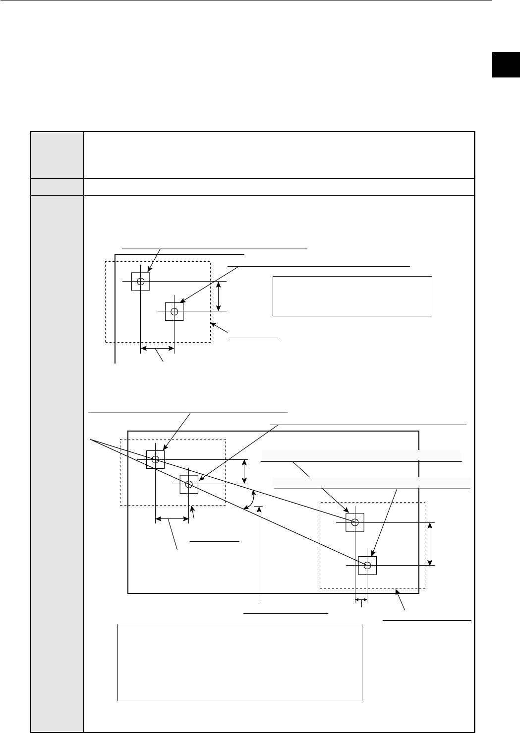
[1] Positional deviation measurement
Purpose
Example
Application
The gray scale search function makes it possible to measure positional deviation as
well as the absolute position.
- It is also possible to detect the position of sub-pixel units with great accuracy.
- A rotation angle of 360° can be detected. (When a one point gray search is selected).
[Determining the location of the positioning (the fiducial mark) mark that
identifies the position of the substrate]
(1) 1 point search: Detecting the deviation in position in X and Y directions
- The deviation angle θ, determined in the 2-point search, is used to readjust the
rotation of the image for measurements 1 to 4.
(2) 2 point search: Determining positional deviation in X and Y directions as well
as rotational deviation
Used to determine the position of machine parts and substrates.
X2-X1
Y2-Y1
Search area
Inspection Image: Center coordinates (X2,Y2)
Reference image: Center coordinates (X1,Y1)
[Measured result]
Center coordinates: (X2,Y2)
Amount of deviation: X2-X1, Y2-Y1
[Measured result]
- Center coordinates of image a: (Xa2,Ya2)
- Amount of deviation of image a: Xa2-Xa1, Ya2-Ya1
- Center coordinates of image b: (Xb2,Yb2)
- Amount of deviation of image b: Xb2-Xb1, Yb2-Yb1
- Deviation angle: θ
Xa2-Xa1
Ya2-Ya1
θ
Search area
(image a)
Yb2-Yb1
Xb2-Xb1
Search area (image b)
Anglar deviation:
θ
Inspection image a: Center coordinates (Xa2,Ya2)
Reference image a: Center coordinates (Xa1,Ya1)
Inspection image b: Center coordinates (Xb2,Yb2)
Reference image b: Center coordinates (Xb1,Yb1)