
User`s manual


Table Of Contents
- Safety Precautions
- Table of contents
- Chapter 1: Outline
- 1-1 Features
- 1-2 Controller
- 1-3 Measurement program
- [1] Positional deviation measurement
- [2] Degree of match inspection
- [3] Lead inspection
- [4] BGA/CSP inspection (IV-S32M/S33M)
- [5] Area measurement by binary conversion
- [6] Object counting by binary conversion
- [7] Object identification by binary conversion
- [8] Point measurements
- [9] Distance and angle measurement
- [10] Multiple position measurement (IV-S33M)
- [11] Multiple degree of match inspection (IV-S33M)
- Chapter 2 : Precautions for Use
- Chapter 3 : System Configuration
- Chapter 4 : Part Names and Functions
- Chapter 5 : Connection and Installation Methods
- Chapter 6 : Setting and Operating Outlines
- Chapter 7 : Simplified Menu Operation
- 7-1 Operation screen
- 7-2 Image display
- 7-3 Setting functions that are different with each controller
- 7-4 Setting procedures
- 7-5 Setting the operation conditions
- 7-6 Setting object types
- 7-7 Setting the shutter speed
- 7-8 Setting the positioning conditions
- 7-9 Setting the existence inspection conditions
- 7-10 Measurement triggering
- 7-11 Saving data
- 7-12 Specify the system conditions
- Chapter 8 : Specifications
- Chapter 9 : Operation Examples
- Glossary
- Appendix
- Alphabetical Index
3-4
System Configuration
3
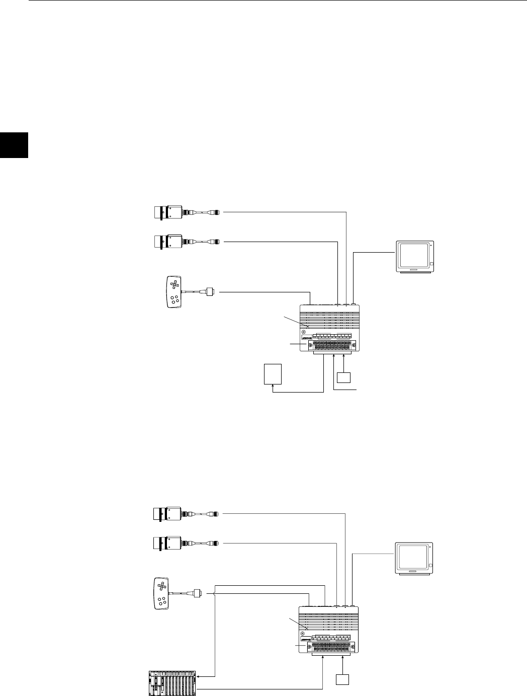
3-2 System configuration examples
This section outlines the system configurations for measurement using an external trigger, such as
measurement using a photo sensor, measurement using CCD trigger, and measurement triggered by a
command from a personal computer.
See "Setting the Input/Output Conditions" in the IV-S30 User’s Manual (function and operation).
[1] System configuration example for measurement triggered by an external
trigger, such as a photo sensor
(1) When IV-S30 is used in a stand-alone mode
- Purpose/application
Measurement is started by an external trigger (a photo sensor or proximity sensor), and the
measurement result is output externally (warning lamp). The object type number is selected by
an external switch.
(2) When a programmable controller is connected
- Purpose/application
Measurement is started by an external trigger (a photo sensor or proximity sensor), and the
measurement data is output to a programmable controller. The object type number is selected
by the programmable controller.
IV-S3*M
OUTPUT
INPUT
POWER
Y7Y0 Y1 Y2 Y3 Y4 Y5 Y6
COM
COM
+24V
X7X0 X1 X2 X3 X4 X5 X6
READY
0V
VIDEO
CAMERA1
CAMERA2
USB
RS232C/RS422
REMOTE
Power supply (24 VDC)
Monitor
Camera 1 (image)
Camera 2 (image)
Remote key pad
Controller
External trigger
(a photo sensor or proximity
sensor, etc.)
Object type selection switch
External
output
Warning lamp etc.
IV-S3*M
OUTPUT
INPUT
POWER
Y7Y0 Y1 Y2 Y3 Y4 Y5 Y6
COM
COM
+24V
X7X0 X1 X2 X3 X4 X5 X6
READY
0V
VIDEO
CAMERA1
CAMERA2
USB
RS232C/RS422
REMOTE
Controller
Power supply
(24 VDC)
Data (computer link)
Monitor
Camera 1 (image)
Camera 2 (image)
Remote key pad
External trigger
(a photo sensor or proximity
sensor, etc.)
Object type selection
(parallel I/F)
Programmable
controller