
User`s manual


Table Of Contents
- Safety Precautions
- Table of contents
- Chapter 1: Outline
- 1-1 Features
- 1-2 Controller
- 1-3 Measurement program
- [1] Positional deviation measurement
- [2] Degree of match inspection
- [3] Lead inspection
- [4] BGA/CSP inspection (IV-S32M/S33M)
- [5] Area measurement by binary conversion
- [6] Object counting by binary conversion
- [7] Object identification by binary conversion
- [8] Point measurements
- [9] Distance and angle measurement
- [10] Multiple position measurement (IV-S33M)
- [11] Multiple degree of match inspection (IV-S33M)
- Chapter 2 : Precautions for Use
- Chapter 3 : System Configuration
- Chapter 4 : Part Names and Functions
- Chapter 5 : Connection and Installation Methods
- Chapter 6 : Setting and Operating Outlines
- Chapter 7 : Simplified Menu Operation
- 7-1 Operation screen
- 7-2 Image display
- 7-3 Setting functions that are different with each controller
- 7-4 Setting procedures
- 7-5 Setting the operation conditions
- 7-6 Setting object types
- 7-7 Setting the shutter speed
- 7-8 Setting the positioning conditions
- 7-9 Setting the existence inspection conditions
- 7-10 Measurement triggering
- 7-11 Saving data
- 7-12 Specify the system conditions
- Chapter 8 : Specifications
- Chapter 9 : Operation Examples
- Glossary
- Appendix
- Alphabetical Index
4-3
Part Names and Functions
4
(3) High-speed camera (IV-S30C3)
- To connect an IV-S30C3 camera, use the IV-S33M controller and camera cable shown above.
Do not connect to the IV-S31M/S32M.
(4) Micro, high-speed camera (IV-S30C4)
- To connect an IV-S30C4 camera, use the IV-S33M controller and camera cable shown above.
Do not connect to the IV-S31M/S32M.
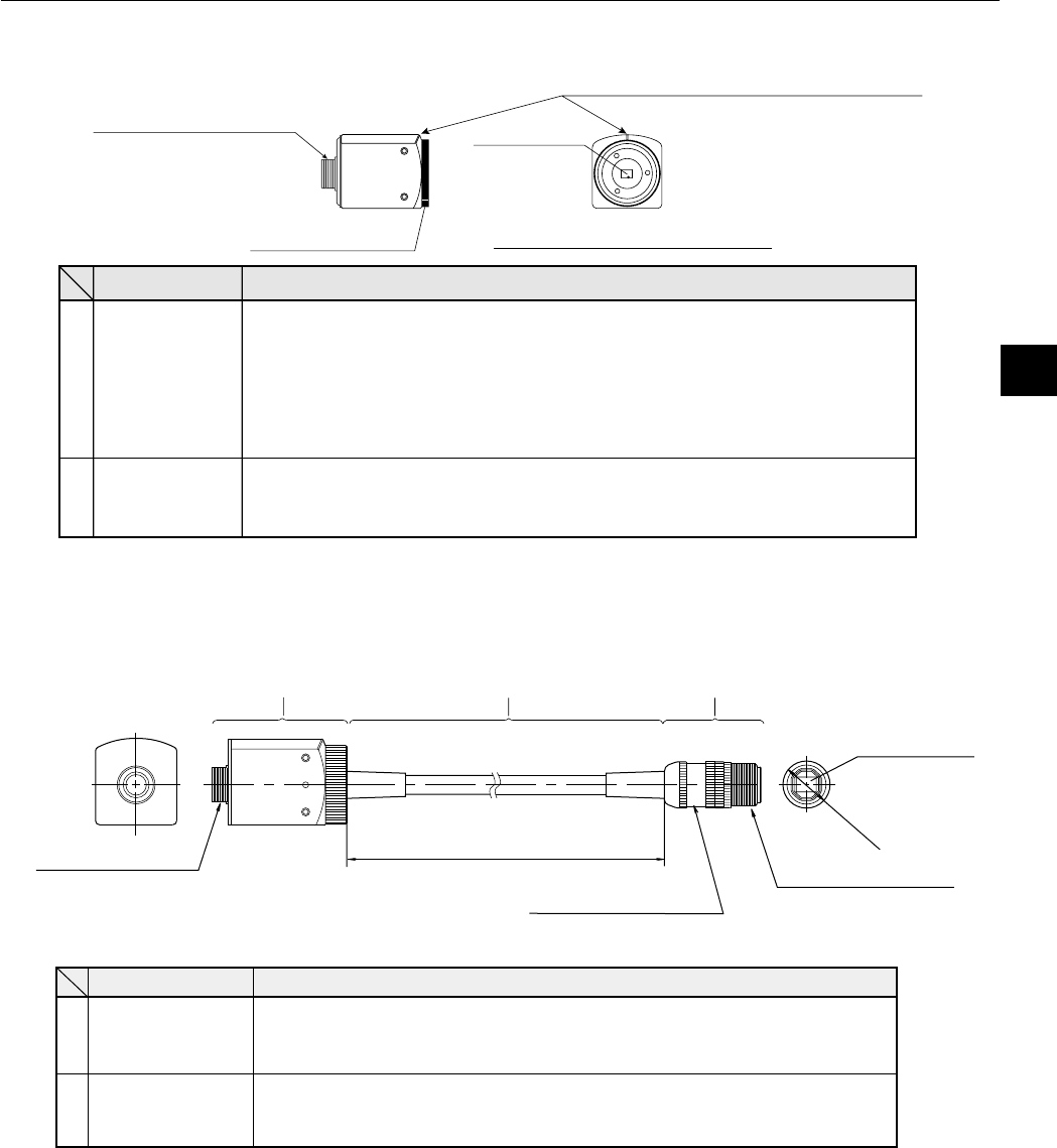
2 Cable connector
CCD section
1 Lens holder
Front view (view A) of the CCD
Lock screw (for securing the lens holder)
⇒
A
Lens holder
FunctionName
The holder is used to make fine adjustment to the distance (back plane fo-
cus) between the CCD section and camera lens using a focus fixed lens.
(The distance has been adjusted before shipment. Usually, it does not
need to be adjusted.)
- To adjust it, loosen the upper lock screw, and turn the lens holder coun-
ter-clockwise. The maximum allowable distance is 1.5 mm.
Cable
connector
Connect this connector to the camera cable (IV-S30KC3/S30KC5
/S30KC7).
Note: This cable cannot be used to connect the IV-S30KC7.
2
1
Lens mount section
(M 15.5 x 0.5 mm)
Cable connector
2 Camera body
1 Camera head
Cable length: 1 m
Head cable
CCD section
φ17mm
Camera head
installation section
emaN noitcnuF
1
daeharemaC
s.nel)elbaliavayllaicremmoc(allatsnI
dna,mm71sidaeharemacehtforetemaidlanretxemumixamehT-
m.m5.0x5.51Msitnuomsnelrofenoeht
2
ydobaremaC
-VI(elbacaremacehtforotcennocaremacehtottcennoC
).7CK/5CK
/3CK03S
.7CK03S-VIehttcennocotdesuebtonnacelbacsihT:etoN
φ