
User`s manual


Table Of Contents
- Safety Precautions
- Table of contents
- Chapter 1: Outline
- 1-1 Features
- 1-2 Controller
- 1-3 Measurement program
- [1] Positional deviation measurement
- [2] Degree of match inspection
- [3] Lead inspection
- [4] BGA/CSP inspection (IV-S32M/S33M)
- [5] Area measurement by binary conversion
- [6] Object counting by binary conversion
- [7] Object identification by binary conversion
- [8] Point measurements
- [9] Distance and angle measurement
- [10] Multiple position measurement (IV-S33M)
- [11] Multiple degree of match inspection (IV-S33M)
- Chapter 2 : Precautions for Use
- Chapter 3 : System Configuration
- Chapter 4 : Part Names and Functions
- Chapter 5 : Connection and Installation Methods
- Chapter 6 : Setting and Operating Outlines
- Chapter 7 : Simplified Menu Operation
- 7-1 Operation screen
- 7-2 Image display
- 7-3 Setting functions that are different with each controller
- 7-4 Setting procedures
- 7-5 Setting the operation conditions
- 7-6 Setting object types
- 7-7 Setting the shutter speed
- 7-8 Setting the positioning conditions
- 7-9 Setting the existence inspection conditions
- 7-10 Measurement triggering
- 7-11 Saving data
- 7-12 Specify the system conditions
- Chapter 8 : Specifications
- Chapter 9 : Operation Examples
- Glossary
- Appendix
- Alphabetical Index
5-23
Connection and Installation Methods
5
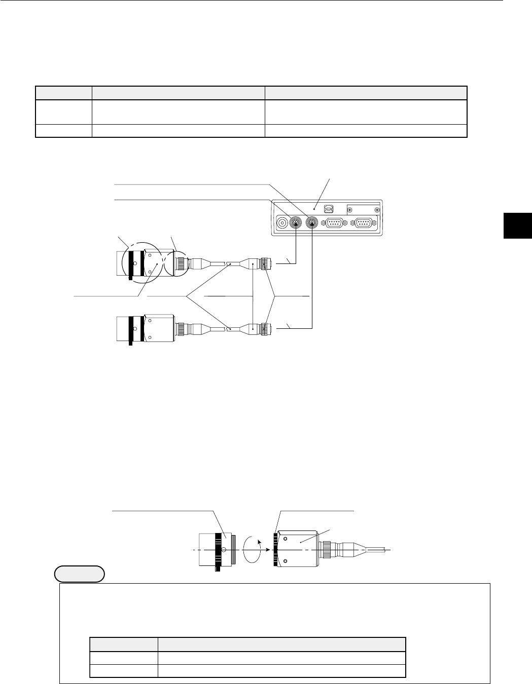
5-3 Installing and connecting the IV-S30C1/C2/C3/C4 camera
[1] Installing and connecting the IV-S30C1/C3
(1) Connections
Up to two IV-S30C1 standard cameras or IV-S30C3 high-speed cameras can be connected to the
following controllers using camera cables.
Note 1: Do not connect the IV-S30C3 to the IV-S31M/S32M. The IV-S30C3 cannot be used with the
IV-S30KC7.
1 Connect the camera cable(s) to the CAMERA 1 and CAMERA 2 connectors on the controller.
- To connect them, match the keyed portion of the connectors and press in. When they are firmly
connected, you will hear a click.
- To unplug a connector, hold the plug housing and pull it straight out.
- Any camera plugged into the CAMERA 1 connector will be system camera 1 and any camera
plugged into the CAMERA 2 connector will be system camera 2 in the IV-S30 system.
Note 2: Make sure to turn OFF the power before connecting or disconnecting the cameras.
Note 3: If there is only one camera, make sure to connect it as system camera 1.
2 Plug the other end of the camera cable into the IV-S30C1/C3, and tighten the securing ring on the
plug housing.
3 Screw the IV-S20L16 camera lens (or similar) into the lens holder on the IV-S30C1/C3 until it is
secure.
Remarks
- You cannot use different types of cameras at the same time with the same controller
(standard, high-speed and EIA cameras cannot be mixed). When an IV-S30C1 or IV-S30C3
is connected to the controller, the other cameras that can be connected to the controller are
as follows:
Lens holder
IV-S30C1/C3
Camera lens
(IV-S20L16 or similar)
aremaC saremacdnoceselbitapmoC
1C03S-VI)aremacorciM(2C03S-VI
3C03S-VI)aremacdeeps-hgih,orciM(4C03S-VI
aremaC tcennocotrellortnoC desuebotselbaC
1C03S-VIM33S-VI,M23S-VI,M13S-VI
,)m5(5CK03S-VI,)m3(3CK03S-VI
,)m7(7CK03S-VI
3C03S-VIM33S-VI )m5(5CK03S-VI,)m3(3CK03S-VI
Camera
cable
Camera 1
Camera 2
Camera
(IV-S30C1/C3)
Camera 1 connector: CAMERA 1
Camera 2 connector: CAMERA2
Plug
Controller (side view)
Connector
1
1
2
3