
User`s manual


Table Of Contents
- Safety Precautions
- Table of contents
- Chapter 1: Outline
- 1-1 Features
- 1-2 Controller
- 1-3 Measurement program
- [1] Positional deviation measurement
- [2] Degree of match inspection
- [3] Lead inspection
- [4] BGA/CSP inspection (IV-S32M/S33M)
- [5] Area measurement by binary conversion
- [6] Object counting by binary conversion
- [7] Object identification by binary conversion
- [8] Point measurements
- [9] Distance and angle measurement
- [10] Multiple position measurement (IV-S33M)
- [11] Multiple degree of match inspection (IV-S33M)
- Chapter 2 : Precautions for Use
- Chapter 3 : System Configuration
- Chapter 4 : Part Names and Functions
- Chapter 5 : Connection and Installation Methods
- Chapter 6 : Setting and Operating Outlines
- Chapter 7 : Simplified Menu Operation
- 7-1 Operation screen
- 7-2 Image display
- 7-3 Setting functions that are different with each controller
- 7-4 Setting procedures
- 7-5 Setting the operation conditions
- 7-6 Setting object types
- 7-7 Setting the shutter speed
- 7-8 Setting the positioning conditions
- 7-9 Setting the existence inspection conditions
- 7-10 Measurement triggering
- 7-11 Saving data
- 7-12 Specify the system conditions
- Chapter 8 : Specifications
- Chapter 9 : Operation Examples
- Glossary
- Appendix
- Alphabetical Index
5-36
Connection and Installation Methods
5
148 89
7911138
238
70 15
100
1
IV-S33M
OUTPUT
INPUT
POWER
Y7Y0 Y1 Y2 Y3 Y4 Y5 Y6
COM
COM
+24V
X7X0 X1 X2 X3 X4 X5 X6
READY
0V
VIDEO
CAMERA1
CAMERA2
USB
RS232C/RS422
REMOTE
1 2
IV-S30EA1
(Unit: mm)
*Main interface cable
IV-S33M
controller
CAMERA1
CAMERA2
+24V
0V
FG
CONTROLLER
IV-S30EA1
POWER
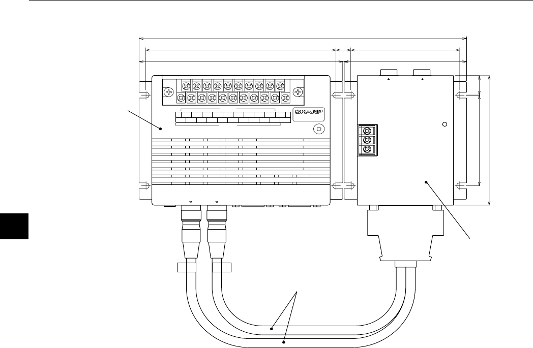
(2) Installation example
* The main interface cable should not be bent to a radius smaller than 40 mm.
(External dimensions of the main interface cable - See page 5-32.)