
User`s manual


Table Of Contents
- Safety Precautions
- Table of contents
- Chapter 1: Outline
- 1-1 Features
- 1-2 Controller
- 1-3 Measurement program
- [1] Positional deviation measurement
- [2] Degree of match inspection
- [3] Lead inspection
- [4] BGA/CSP inspection (IV-S32M/S33M)
- [5] Area measurement by binary conversion
- [6] Object counting by binary conversion
- [7] Object identification by binary conversion
- [8] Point measurements
- [9] Distance and angle measurement
- [10] Multiple position measurement (IV-S33M)
- [11] Multiple degree of match inspection (IV-S33M)
- Chapter 2 : Precautions for Use
- Chapter 3 : System Configuration
- Chapter 4 : Part Names and Functions
- Chapter 5 : Connection and Installation Methods
- Chapter 6 : Setting and Operating Outlines
- Chapter 7 : Simplified Menu Operation
- 7-1 Operation screen
- 7-2 Image display
- 7-3 Setting functions that are different with each controller
- 7-4 Setting procedures
- 7-5 Setting the operation conditions
- 7-6 Setting object types
- 7-7 Setting the shutter speed
- 7-8 Setting the positioning conditions
- 7-9 Setting the existence inspection conditions
- 7-10 Measurement triggering
- 7-11 Saving data
- 7-12 Specify the system conditions
- Chapter 8 : Specifications
- Chapter 9 : Operation Examples
- Glossary
- Appendix
- Alphabetical Index
5-37
Connection and Installation Methods
5
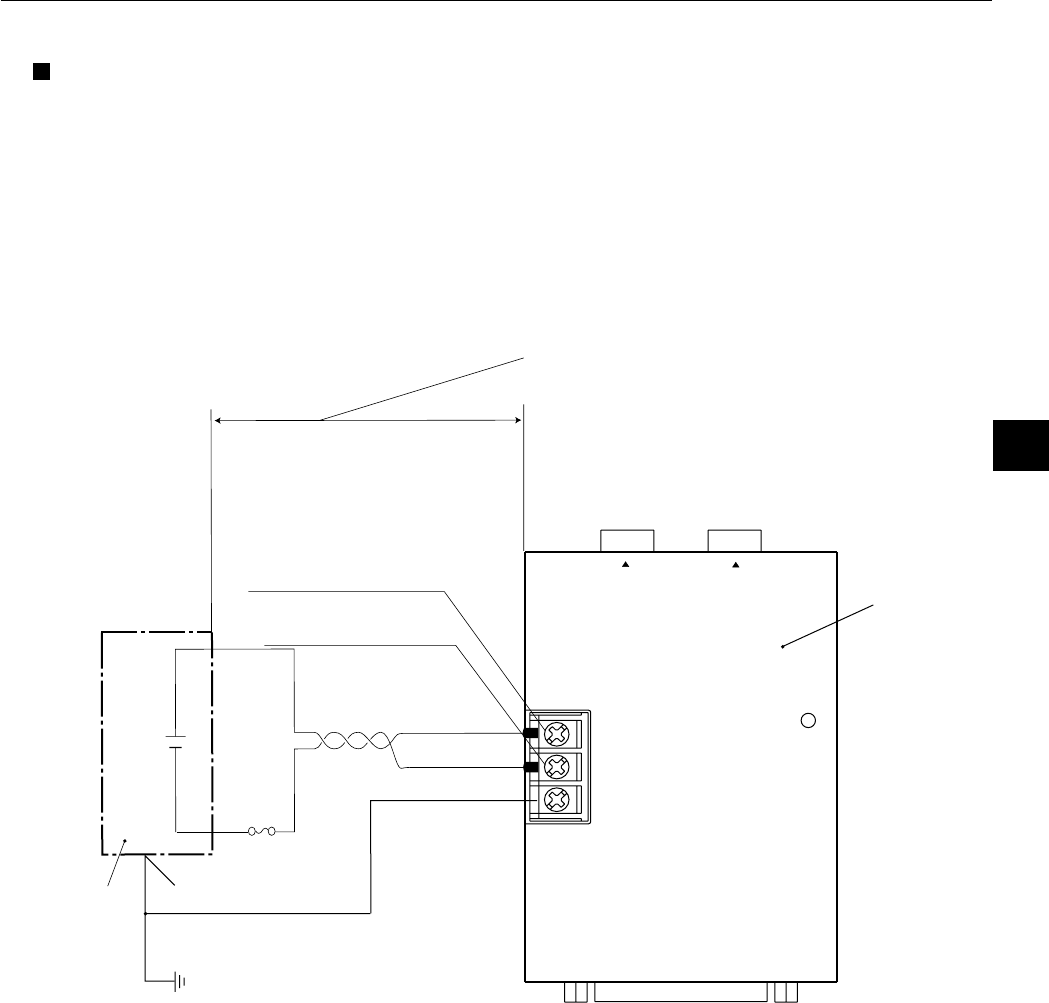
[4] Wiring of the IV-S30EA1
Connecting a power supply
Connect a commercially available constant-voltage power supply to the power terminals (POWER: +24
V, 0 V) on the IV-S30EA1. Use a 24 VDC ± 10%, 500 mA or more constant-voltage power supply.
- Use an individual and dedicated power supply to supply power to the IV-S30EA1. If the power supply
is used to power other equipment, measurement errors may occur.
- Check the polarity of the power supply terminals, +24 V and 0 V. If power is supplied with the polarity
inverted, the controller may be damaged.
- Only connect or disconnect the camera cable and other equipment while the power is OFF.
Note: To improve the noise resistance of the constant-voltage power supply connected to the
IV-S30EA1, observe the following precautions.
- Ground the FG terminal of the constant-voltage power supply according to the class 3
grounding.
- The power line between the IV-S30EA1 and the constant-voltage power supply must be as
short as possible. (Recommended distance: less than 1 m)
Do not run the power supply line near any noise generating sources, such as electric motor
lines.
- Use twisted-pair wire for the power supply line.
CAMERA1
CAMERA2
+24V
0V
FG
CONTROLLER
IV-S30EA1
POWER
DC24V
(+)
(−)
IV-S30EA1
This distance must be
as short as possible.
(Recommended distance:
less than 1 m)
Frame ground
terminal
Fuse
(1A)
Constant-voltage
power supply
Power supply terminal
(POWER: + 24V)
Power supply terminal
(POWER: 0V)