
User`s manual


Table Of Contents
- Safety Precautions
- Table of contents
- Chapter 1: Outline
- 1-1 Features
- 1-2 Controller
- 1-3 Measurement program
- [1] Positional deviation measurement
- [2] Degree of match inspection
- [3] Lead inspection
- [4] BGA/CSP inspection (IV-S32M/S33M)
- [5] Area measurement by binary conversion
- [6] Object counting by binary conversion
- [7] Object identification by binary conversion
- [8] Point measurements
- [9] Distance and angle measurement
- [10] Multiple position measurement (IV-S33M)
- [11] Multiple degree of match inspection (IV-S33M)
- Chapter 2 : Precautions for Use
- Chapter 3 : System Configuration
- Chapter 4 : Part Names and Functions
- Chapter 5 : Connection and Installation Methods
- Chapter 6 : Setting and Operating Outlines
- Chapter 7 : Simplified Menu Operation
- 7-1 Operation screen
- 7-2 Image display
- 7-3 Setting functions that are different with each controller
- 7-4 Setting procedures
- 7-5 Setting the operation conditions
- 7-6 Setting object types
- 7-7 Setting the shutter speed
- 7-8 Setting the positioning conditions
- 7-9 Setting the existence inspection conditions
- 7-10 Measurement triggering
- 7-11 Saving data
- 7-12 Specify the system conditions
- Chapter 8 : Specifications
- Chapter 9 : Operation Examples
- Glossary
- Appendix
- Alphabetical Index
7-2
Simplified Menu Operation
7
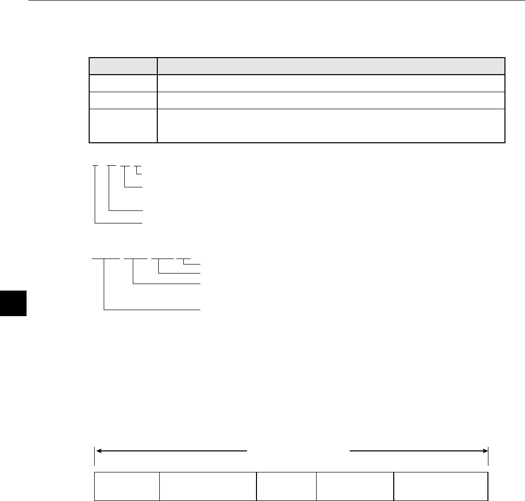
1 Object type No. (00 to 15: IV-S31M, 00 to 31: IV-S32M, 00 to 63 : IV-S33M)
2 Final evaluation result
3 F C1 L ●
4 LOCK FULL VX.X ■
System program version number
Image scanning mode (this is only displayed on the IV-S33M)
: FULL = full mode, HALF = half mode, F + H = full and half mode
Lock the MAIN OPS MENU (operation screen)
("LOCK" is not displayed while the screen is unlocked. See page 6-6.)
Flashes during communications
Display
OK
NG
"OK" is displayed when all of the individual evaluation results are acceptable.
"NG" is displayed if any single evaluation result is unacceptable.
(Error
message)
Description
An error code and the measurement number that caused the error are
displayed on the upper line. The error message is displayed on the lower line.
Actively operating: Flashing
Image brightness: H = Original brightness of captured image
L = Brightness reduced to half that in the captured image
Output monitor status: C1 = Camera 1, C2 = Camera 2
Image display mode: F = Freeze mode
T = Through mode (raw image)
5 Measurement No. (0 to 2), Camera No. (1 or 2), and the measurement to be carried out
POSITIONING: MEAS 0 CAM 1 or MEAS 0 CAM 2
POS-CORRECT: MEAS 0 CAM 1 or MEAS 0 CAM 2
EXISTENCE: MEAS 1 CAM 1 or MEAS 2 CAM 2
CCD exposure time
(Shutter speed)
CCD image
capture time
Measurement result
display time
Actual measuring time
Type change
time
(Only when changing the type)
Image
processing time
- The measuring time does not include the serial communication time.
- To decrease the measuring time:
1. Increase the shutter speed (page 7-12),
2. Change the CCD image capture mode (CAPTURE AN IMAGE) to PARTIAL-IMG (see page
7-7), and
3. Set the result displays (MESSAGE DISPLAY, PATTERN DISPLAY, SHOW BINARY IMG) to
"NO" (see page 7-8 to 7-10).
6 Measuring time
- The screen shows the measuring time determined by the following (from measurement start to
measurement end).
7 Measurement result
- After you save* the specified conditions, the settings for the "Measured result screen" and
"Image brightness: H/L" on the MAIN OPS MENU (operation screen) will be kept in memory,
even when the power is turned OFF and ON again.
* To store the data, select "SAVE" on the menu bar.