
Specifications
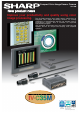


Compact Color Image Sensor Camera IV
-
C35M
■ Specifications of IV
-
C35M controller
■ Specifications of the color camera IV-C30C5
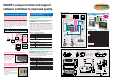
■ Measurement menus that can be used for various inspections
Optical system Lens mount method Cmount
Picture taking
element
Method Interline transmission method, 1 CCD color
Reading system Full pixel type, partial image scanning is available
Reading 33.3 ms [full mode]
Size 1/3 inch
No. of effective pixels 512 (horizontal) × 480 (vertical)
Pixel shape Square
Shutter
Shutter speed (s)
Settable between for each object type, between 1/30
and 1/10,000 sec.
Method Random shutter
Connector Round, 12-pin male connector
Connection to controller
Using custom camera cables (IV-S30KC3: 3 m, IV-
S30KC5: 5 m)
Operation ambient temperature/
Operation ambient humidity
0to45
o
C/35 to 85% RH (non-condensing)
Operation atmosphere No corrosive gases or dust
Outside dimensions (mm) 30 (W) × 32 (H) × 40 (D)
Weight 50 g (not including the lens)
Color
extraction
mode
Color evaluation
Evaluate whether the extracted color matches the
reference color
Color unevenness
inspection
Evaluate color unevenness based on the size of certain
extracted areas of color that are outside the reference color
range.
Color position
measurement
Measure the position coordinates of a workpiece with the
same extracted color as the reference color.
Area measurement by
binary conversion
Measure the extracted color area on a workpiece.
Object identification by
binary conversion
Check for the existence and measure the size of the
extracted color areas on multiple workpieces
Count measurement
by binary conversion
Count the number of separate areas on a workpiece with
extracted color.
Color
filter
mode
Fault inspection
Detect flaws or dirt on a workpiece that are the same color
as was emphasized using a color filter function.
Position deviation
measurement
Measure positional deviation between an area on a
workpiece whose color was emphasized (using the color
filter function) and a reference position.
Degree of match
inspection
Evaluate whether a workpiece is good or not good by the
degree of match with a reference image.
Area measurement by
binary conversion
Measure the area of the color on a workpiece that was
emphasized using a color filter.
Count objects by
binary conversion
Count the number of separate colored areas on a
workpiece that were emphasized by using a color filter.
Object identification by
binary conversion
Check for the existence and measure the size of the areas
of emphasized color on multiple workpieces.
Point measurement
Evaluate whether workpieces are present or not at multiple
specified points.
Lead inspection
Measure the lead width and length, and the distance
between the leads in an emphasized color.
BGA/CSP inspection
Measure the number of objects, area, filet diameter and
distance between centers of gravity on BGA/CSP chips
whose color has been emphasized.
Multiple position
measurement
Measure the position and number of workpieces with a
degree of match to the reference image that is larger than
aspecified level.
Multiple degree of
match inspection
Measure the degree of match of each workpiece by
comparison with a reference image. Count the ones with a
degree of match larger than the specified level.
- Windows 95/98/Me/NT4.0/2000 and Excel are registered trademarks of the Microsoft Corporation, USA. - Company names, product names, and merchandise names described in
this leaflet are the trademarks or registered trademarks of each respective company. - The specifications may be changed without prior notice. The color of the actual product may
vary from that shown in this brochure. - Some models in this leaflet may be out of stock. Please contact your sales agent for selection of currently available models. - Images used in
the leaflet may be different from the images actually displayed on the monitor.
To use this device effectively and safely!
- Make sure to read the instruction manual before use. Make sure to supply the specified power and voltage.
*1 This is true when the search area is 256 x 256 pixels, the model is 64 x 64 pixels, and
the compression is set to 3.
*2 Measurement 0 is only used for positional deviation measurements.
Termi-
nal
block
Input
Number of points
8 points: One external trigger, 5 object type change,
2exernal input
Common for input 1 point: + or - common
Rated input voltage 12/24 VDC
Input voltage range 10.8 to26.4VDC
output
Number of points
9points: One READY, 8 user spacific logical output
(Y0 to Y7)
Common for output 1 point: + or - common
Rated output voltage 12/24 VDC
Load voltage range 10.8 to26.4VDC
Rated max. output current 100 mA DC
Output system MOS FET open drain system
Power Power terminals 2 points: 24 VDC and 0 V
Power supply voltage / power consumption 24 VDC (±10%), 12W
Operating ambient temperature/humidity Approx. 600 g
External dimentions
130 (W) X100 (D) X 42 (H) mm (excluding
protruding portions)
Weight Approx. 600 g
Image sampling system
16,770,000 colors, 256 level gray scale, binary
conversion, edge detection
Number of pixels
512 (horizontal) x 480 (vertical), approx. 240, 000
pixels
Image memory
One screen for displaying captured images. One
color screen for displaying camera information and
messages
No.of assignable object type 32
Maximum number of reference images
stored / number of whole screens stored
600 / 8 screens
Gray search time 9ms *1
Gray search, edge detection precision Pixel, sub-pixel
Image processing
Color filter (R, G, B, and optional)
Color extraction (hue, saturation, and brightness)
Gray search
Color image
pre-processing
Saturation correction Adjust saturation level
Brightness correction Adjust brightness level
Gray image
pre-processing
Shading correction Dividing, subtracting, and filtering
Comparative calculation
between images
Subtracting, absolute value of difference (between
camera 1 and reference image, between camera 2
and reference image, between camera 1 and
camera 2)
Gray level changes
Magnification by "n" processing g(+/-) correction,
histogram expansion, mid-range emphasis
Space filter
Smoothing (center/average), edge emphasis, edge
extraction, horizontal edge, vertical edge
Binary threshold value
Fixed and threshold value corrections (variation
difference/variation rate)
Binary noise elimination
Expansion to contraction, contraction to expansion,
area filter
Binary image mask
Specified window (rectangle, circle, oval), any binary
image mask
Positional correction method X/Y correction, rotation correction
Number of measurement programs
Maximum 6 per object type (measurement 0 -
camera 1, measurement 0 - camera 2,
measurements 1 to 4) *2
Window shape
Rectangle, circle, oval (when using area
measurement by binary conversion, object counting
by binary conversion, object identification by binary
conversion)
Distance and angle measurement
Measure distance (between two points, X
coordinate, Y coordinate), measure angle (3 points,
2 points against horizontal line, 2 points against
vertical line), auxiliary point (center, circle center,
gravity center, line over 2 points, crossing point of
two straight lines)
Arithmetic operation
Four basic operations (+, -, X, /), root, absolute
value, TAN, ATAN, maximum, minimum, average ,
total.
NG image memory function Maximum 128 images (8 whole screens)
Memory card slot One (compatible with a 192 Mbyte capacity card)
Calendar/timer Year, month, day, hour, minute
Other functions
Display measuring time, light level monitor function,
crosshair cursor display, change display language
between Japanese and English, Run screen lock
function, display setting menu "yes/no", change
image display (through/freeze), change image
brightness (bright/dark)
Micro PLC
section
Input relays Parallel input: 8 points
Output relays
Parallel output: 8 points, general-purpose serial
interface Computer link: 16 points
Auxiliary relays 128 points, special area 18 points
Timers
8 points, timer setting range: 0.01 to 9.99 seconds
(countdown timer)
Counter
8 points, counter setting range: 000 to 999 (counts
down)
External
interface
Parallel interface Input: 8 points, Output: 9 points
General-
purpose serial interface
RS232C/RS422 (2.4 to 115.2 kbps)
Computer link
Built-in compatibility with certain SHARP, OMRON,
Mitsubishi, and Yokogawa models
USB USB device node, 12 Mbps
Image output 1channel, EIA 525 lines, 2:1 interlaced
Number of cameras Maximum of 2
Compatible cameras
Color: IV-C30C5, High-speed monochrome: IV-
S30C3/IV-S30C4
Make settings
Using the IV-S30RK1 remote keypad for IV series
and the IV-S30SP parameter setting support
software for IV series
Measurement
start input
Internal trigger Color CCD trigger, CCD trigger (gray search)
External trigger
Trigger input (parallel I/F), general-purpose serial
I/F, keypad trigger (for manual measuring)
SMS-068E 10803 O.1
The details in this pamphlet were correct as of March 2002.
SHARP MANUFACTURING SYSTEMS CORPORATION
4-1-33 Atobe Honmachi, Yao, Osaka, 581-8581, Japan
TEL: +81-729-91-0587 FAX: +81-729-91-0626
● Information about SHARP control equipments is available at our
web site http://sharp-world.com/sms/