
Specifications
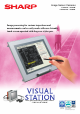


Next-generation image sensor camera
“VISUAL STATION”
■Specifications of camera lens (IV-S20L16)
■Specifications of IV-S51M controller
Optical
system
maintenance
Lighting adjustment
Light level automatic
adjustment
Image sampling system Monochrome 256 gray level
Image memory One screen for one captured image per camera
No. of assignable object type 64 object types
No. of camera to be connected Up to 2 cameras
Image processing Gray, binary conversion
Image
capture time
33.3 ms
Standard camera
High speed camera
16.7 ms (full mode), 8.3 ms (half mode)
Gray search time 8ms (model: 64×64, search area: 256×256, when the speed is prioritized)
Rotation correction time
142 ms
(
conditions: 360゜, freeze, priority on speed, size 128×64, search area 512×480
)
Gray search, edge detection precision
Sub-pixel
Gray image
pre-processing
Histogram wideningGray level change
Noise elimination Smoothing (average/ center)
Outline extraction
Edge extraction (primary differentiation, secondary differentiation), horizontal edge, vertical edge
Binary threshold value
Fixed and threshold value correction (variation difference/variation rate)
Expansion, contraction,
and area filter
Expansion→contraction→contraction → expansion,
contraction → expansion → expansion → contraction, space filter
Positional correction method
Window shape
X/Y correction, rotation correction
Position detection
Inspection
program
Rectangle, circle, oval, polygon, and free shape
Position &
attitude angle
Shape degree of
match inspection
Point sensor
Existence of work
and size inspection
Output: yes or no
Workpiece counting
No. of projected parts
and alignment
Object: 1. all the workpieces, 2. designated workpieces Output: number of object detected
Distance & angle
measurement
The number of projected parts, interval, width (point alignment)
Workpiece dimension
measurement
Object: 1. single workpiece, 2. multiple workpieces can be processed simultaneously
Output: distance (between 2 points/X coordinate/Y coordinate),
angle (3 points/2 points against vertical line/2 points against horizontal line)
Output: number of workpiece, total area, area for each label, diameter
of the projection width, circumference length, main axes angle
Number of measurement
program
Arithmetic operation
Maximum 8 measurements/type (measurement item 0 - camera 1,
measurement item 0 - camera 2, and measurement item 1 ∼ 6)
NG image memory function Maximum 128 images (8 whole scenes)
Four basic operations (+,−, ×, ÷), root, absolute value,
TAN, ATAN, maximum, minimum, average, and total
Calendar/timer Year, month, day, hour, minute and second
Optical system
configuration
setting
1. Focus adjustment, 2. contrast adjustment
Image adjustment 1
1. Image distortion diagnosis & compensation, 2. calibration
Image adjustment 2
Other functions
Displaying measuring time, monitoring illuminance, switching language
between Japanese and English, running screen lock
function, and change image display (through/freeze)
Image processing procedure
automatic generating expert
(binary processing)
Object: position detection, position & attitude angle, size inspection,
workpiece count inspection, distance & angle measurement,
workpiece dimension measurement, and defect inspection
Auxiliary relays
Micro PLC
section
Internal auxiliary 1024 points (C0 ∼ C1023), system auxiliary 64 points (S0 ∼S63)
Timer 16 points (TM0 ∼ TM15), timer setting range (0.01 ∼ 9.99 seconds), (down counter)
16 points (CN0 ∼ CN15), counter setting range (1 ∼ 999 seconds), (up counter)Counter
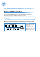
Parallel interface
IPU external
interface
Input: 16 points (X0 ∼ X15), DC12/24V 7mA (DC 24V)
Output: 16 points (Y0 ∼ Y15) DC12/24V 80mA (open corrector)
Serial interface
Extension terminal
RS232C/RS422(2-wire/4-wire system), (2.4 ∼ 115.2kbps) upward calculator, PLC
Internal trigger
Measurement
start input
RS-232C/RS-422 (2-wire system only)
Computer link
Compatible with SHARP, OMRON, Mitsubishi, and Yokokawa models.
External trigger
CCD trigger
Power supply input
Trigger input (parallel interface), serial trigger, and manual trigger (for testing)
Parallel interface
+24V, 0V FG
Control function
Lighting
control
Number of control
Common for input: 1 point
Control port
Interrupt input (trigger) 1 point
Power supply voltage/
power consumption
Input 15 points
Operation ambient temperature/
atmosphere
Common for output: 1point
Storage ambient temperature/
atmosphere
READY 1 point
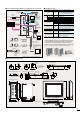
External dimension/weight
HALT output 1 point (interlocking with watchdog timer)
USB host
HMI External
interface
Output 16 points
LAN
Touch panel, and commercially available USB mouse
VGA output port 1 point, IV LCD monitor output 1 point
10/100 base-TX
USB 1.1 specification, 2 channel
81mm (W) × 125mm (D) × 175 mm (H) (protruding portions are not included),
approx. 1.5 kg
- 20 ∼ 70 ℃/35 ∼ 95% RH (non-condensing)
0 ∼ 45 ℃/35 ∼ 95% RH (non-condensing)
DC24V (±10%) 30W
Parallel I/F or RS-232C/RS-422
4 systems, 2 controls/1 system
Dimmer function, lamp ON/OFF (LED), shutter ON/OFF (halogen)
Image output
SVGA (800×600×24bpp) analog output
IV LCD monitor (800×600×18bpp) digital output
Operation input
Image output
Object:1. single workpiece, 2. multiple work pieces can be processed simultaneously
Output: coordinate
Object: 1. single workpiece, 2. multiple workpieces can be processed simultaneously
Output: coordinate, angle
Object: 1. single workpiece, 2. multiple workpieces can be processed simultaneously
Output: Degree of match
Measurement: 1. no individual workpiece, 2. individual workpiece Output: area
*1 Variable by reading partial image.
*2 IV-S30C3/C4 can not be connected to IV-S30KC7(7m).
■
Specifications of IV LCD monitor
(
IV-08MP
)
/ IV LCD monitor cable
(
IV-S50MC2
)
LCD
panel
Screen size
Screen image of the display
Touch panel
RS232C Serial
Power supply voltage/power consumption
Operation ambient temperature/atmosphere
Storage ambient temperature/atmosphere
External dimension/weight
Protection to the environment
8.4-inch, TFT liquid crystal panel, SVGA, custom I/F
65,000 colors
Resistance membrane type, Resolution 1024 × 1024
Reading the touch panel position
DC24V (±10%) 12W
0 ∼ 40 ℃/35 ∼ 90% RH (non-condensing)
-20 ∼ 60 ℃/35 ∼ 90% RH (non-condensing)
242 (W) × 42 (D) × 200 (H), approx. 1.0 kg
Connecting cable (2 m) for IV LCD monitor (IV-08MP)
Equivalent to IP65
(The face of liquid panel only when mounting the main unit)
IV LCD monitor cable
■Specifications of camera
Standard
IV
-
S30C1
Micro
IV
-
S30C2
High speed
IV
-
S30C3
Micro, high speed
IV
-
S30C4
Optical system
Lens mount method
C mount
φ
17 mm mount
Picture
taking
element
Method
Reading system
Interline transmission method, monochrome CCD
Full pixel type, partial image scanning is available.
Reading
time
Standard
High speed
33.3 ms
*1
16.7 ms (full mode), 8.3 ms (half mode) *1
Size 1/3 inch
No. of effective pixels
52 (horizontal) × 480 (vertical)
Pixel shape
Tetragonal lattice
Shutter
Shutter speed
Settable between 1/30 ∼ 1/10,000 sec. (for each object type)
Method
Random shutter
Connector
Round, 12-pin, male connector
Connection using custom camera cables
(IV-S30KC3: 3m, IV-S30KC5: 5m, and IV-S30KC7
*2
: 7m)
Connection to controller
Operation ambient temperature/
humidity/atmosphere
0 ∼ 45 ℃/ 35 ∼ 85% (non-condensing), free from corrosive gases or dust
External
dimensions
Camera body section
IV-S30C2: 30 (W) × 32 (H) × 50mm(D)
IV-S30C4: 30 (W) × 32 (H) × 44.7mm (D)
30 (W) × 32 (H) × 40 mm(D)
Head section
−
φ
17 mm × 35.6mm
Head cable
−
1 m
Weight
IV-S30C2: approx. 125 g
(approx. 12g for head section)
IV-S30C4: approx. 140 g
(approx. 13g for head section)
50 g (not including the lens)
Focal distance
Maximum f-stop
Aperture range
Focal range
Filter installation diameter
Mount system
Compatible cameras
16 mm
1.6
1.6 ∼ 16 close
50 mm ∼ ∞
M25.5, P = 0.75, U1
C mount
IV-S30C1/C3
■
Operating environment of parameter setting support software
(
IV-S50SPM
)
The environment where Windows 2000/XP/98 can be operated.
IBM PC/AT or compatible machines
Pentium 500 MHz or better
128 MB or more
30 MB or more free space
A mouse or pointing device compatible with the Windows 2000/XP/98 environment.
Resolution: 800 × 600 pixels (Recommended: 1024 × 768 dots), 65,000 colors
A printer compatible with the Windows 2000/XP/98 environment
Operating system
Model
CPU
Memory
Hard disk
Mouse
Display
Printer
- Windows 2000/XP/98 are registered trademarks of the Microsoft Corporation, USA. - Company names, product names, and merchandise names described in this leaflet are the
trademarks or registered trademarks of each respective company. - The specifications may be changed without prior notice. The color of the actual product may vary from that shown
in this brochure. - Some models in this leaflet may be out of stock. Please contact your sales agent for selection of currently available models. - Images used in the leaflet may be
different from the images actually displayed on the monitor.
To use this device effectively and safely!
- Make sure to read the instruction manual before use. Make sure to supply the specified power and voltage.
SMS-068E 10803 O.1
The details in this pamphlet were correct as of April 2004.
SHARP MANUFACTURING SYSTEMS CORPORATION
4-1-33 Atobe Honmachi, Yao, Osaka, 581-8581, Japan
TEL: +81-729-91-0587 FAX: +81-729-91-0626
● Information about SHARP control equipments is available at our
web site http://sharp-world.com/sms/
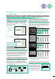
Adjustment of light volume
Monitoring illuminance→ shading diagnosis → optical system automatic adjustment
(1. light volume, 2. shutter speed)