Version 2.2 Produced in Oct.
Thank you for purchasing the network module (JW-20CM), remote I/O slave module (JW-20RS) for the SHARP programmable controller. Read this manual thoroughly to completely familiarize yourself with the operation according to the examples. Besides this manual, the manuals of control module, support tool, and option module are available for the respective programmable controller. We ask you to also read these manuals as well as this manual. Keep this manual for future reference.
Safety Precautions Read this manual and attached documents carefully before installation, operation, maintenance and checking in order to use the machine correctly. Understand all of the machine knowledge, safety information, and cautions before starting to use. In this instruction manual, safety precautions are ranked into "danger" and "caution" as follows. Danger : Wrong handling may possibly lead to death or heavy injury. Caution : Wrong handling may possibly lead to medium or light injury.
3) Use Danger • Don’t touch the terminal while the power is being supplied or you may have an electric shock. • Assemble the emergency stop circuit and interlock circuit outside of the programmable controller. Otherwise breakdown or accident damage of the machine may be caused by the trouble of the programmable controller. Caution • “RUN” or “STOP’” during operation should be done with particular care by confirming safety. Misoperation may lead to damage or accident of the machine.
■ Configuration of this manual The network module JW-20CM has three functions: "remote I/O," "data link," and "computer link" functions. Accordingly, this manual describes about these three functions. Read each section according to your use of any of these functions. Users who use the network module for the first time. Read this manual from chapter 1. First, thoroughly understanding general, precautions, name and function of each section. Then, read the contents from chapter 5 for proper use.
Network module JW-20CM Remote I/O slave module JW-20RS - User’s Manual - Chapter 1. Outline Chapter 2. Safety Precautions Chapter 3. System Configuration Chapter 4. Name and Function of Each Part Chapter 5. Installation Chapter 6. Processing of Cables Chapter 7. Wiring Chapter 8. Remote I/O Chapter 9. Data Link Chapter 10. Computer Link Chapter 11. Support Tools Chapter 12. Specifications Chapter 13.
Table of contents Chapter 1 Outline ................................................................................................................................... 1·1 Chapter 2 Safety Precautions ............................................................................................................... 2·1 2-1 Installation 2·1 2-2 Wiring 2·1 2-3 Treatment 2·3 2-4 Static electricity 2·3 2-5 Maintenance 2·3 Chapter 3 System Configuration ...............................................................
Chapter 11 Support Tools ..................................................................................................................... 11·1 11-1 Record and load by ladder software (JW-50SP) 11·1 11-2 Remote function 11·5 Chapter 12 Specifications ....................................................................................................................12·1 12-1 JW-20CM 12·1 12-2 JW-20RS 12·4 Chapter 13 Appendix ................................................................................
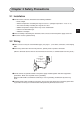
Chapter 1 Outline Using network module JW-20CM, you can construct a communications system (satellite net) which can easily send and receive an ON/OFF signal (machine information) and numerical data (production data) between PCs and a host computer using equipment control. Using remote I/O slave module JW-20RS, you can construct a remote I/O system as master station for PC that installed JW-20CM. PCs which can use JW-20CM and JW-20RS are W70H/100H, JW50/70/100, and JW50H/70H/100H.
Chapter 2 Safety Precautions 2-1 Installation ● Do not install or store the JW-20CM in the following conditions. • Direct sunlight • Ambient temperature exceeding the range of 0 to 55 ˚C (Storage temperature : -20 to 70 ˚C) • The relative humidity exceeding the range of 35 to 90%. • Sudden temperature changes which may cause condensation. • Corrosive or inflammable gas • Vibration or hard jolts ● Prior to installing or detaching the JW-20CM, make sure to turn OFF the power supply to the PCs.
● Communication cables should be laid from the master station to the slave station one by one. Multiple wiring from one point or wiring without terminators may cause communication errors. Joint using a connector 2 ● Arrange total cable length within 1 km. ● Arrange branch cable line from a trunk within 400 mm. ● Prior to any electric welding around the JW-20CM, take out the coaxial cable from the JW-20CM.
2-3 Treatment ● For ventilation, holes are provided in the cabinet to prevent a temperature rise. Do not block the ventilation holes. Good ventilation is necessary. ● Never allow a liquid such as water and chemical solution and a metallic object like a copper wire inside the JW-20CM to avoid a possible hazard. Otherwise, it may be a cause of machine trouble.
Chapter 3 System Configuration (Example of system configuration) Personal computer slave station 02(8) Master station 00(8) Slave station 01(8) JW-20CM JW-20CM PC PC Slave station JW20 Slave station 77(8) 03(8) JW20H JW-22CM J-board V5 JW30H Network module Z-335J 3 Data link system (64 stations max., Total extension length: 1km max.) Compuer link system Slave station 01(8) JW-20RS Slave station 02(8) ZW-20RS Slave station 77(8) JW-20RS Remote I/O system (slave station : 63 stations max.
Chapter 4 Name and Function of Each Part 4-1 JW-20CM ① ② ⑦ ③ 4 ④ (View removing the cover on the setting section) ⑤ ⑥ ① Indication lamps Lamps light ON/OFF indicates operation condition.
③ Support tool connection connector Connect a support tool and set parameter etc. ④ Setting switch Set functions of JW-20CM. · MODE switch .... Select functions 67 2 3 2 3 4 5 6 45 7 8 LG (ON) Set at delivery 1 Remote I/O 0 3 OFF Function 0 2 9 0 1 4 5 6 0 23 7 8 LT (ON) 4 0 9 0 1 ×1 01 STA.NO. ×10 Number BCD EF MODE 8 9A Set at delivery 4 to F Data link (standard function) Computer link Data link (memory capacity save function) Computer link Do not set. ON · S T A . N O. .
4-2 JW-20RS ① ② ⑦ ③ ④ 4 ⑤ ⑥ ① Indication lamps Lamps light ON/OFF indicates operation condition.
③ Support tool connection connector Connect a support tool and set parameter etc. ④ Setting switch Set functions of JW-20RS. · MODE switch .... Select functions 67 0 23 45 7 8 2 3 7 8 2 3 4 5 6 0 9 0 1 4 5 6 2 9 0 1 LT (ON) ON LG (ON) Output hold switch 0 Do not set. 1 Remote I/O (ZW-I/O) 2 Remote I/O (JW-I/O) 3 to F OFF HOLD Do not set. · S T A . N O. .... Set station number × 10, × 1 · L T .... Set ON/OFF of termination resistance · L G ....
Chapter 5 Installation 5-1 JW-20CM (1) Installation of cable for option module Install the optional cable on the basic rack panel that installed JW-20CM.
② Attach the connectors in the optional cable one after another, starting from the left side. Basic rack panel JW-4BU Pay close attention to the installation of the connector.
(2) Installation of JW-20CM Attach the basic rack panel using the two attachment screws. Before installation or removal, make sure to shut OFF the power supply to the PC. (Example) Install on basic rack panel JW-4BU · This module can be installed in any one of the optional slots. · Be careful not to bend the connector pins on the module by applying too much force to them.
5-2 JW-20RS Choose type of basic rack panel of the remote I/O slave module (JW-20RS) considering kinds and number of I/O modules to be installed.
(1) Installation of power supply module Attach the end left of rack panel using the two module attachment screws.
(2) Installation of JW-20RS Install the JW-20RS in the second slot from the left end using the two module attachment screws. Before installation or removal, make sure to shut OFF the power supply to the PC.
Chapter 6 Processing of Cables Make sure to use the recommended models shown below for cables and connectors. Name Cable Model High frequency coaxial cable Crimping tools Stripper for high frequency coaxial cable ME-5C-2V ME-42H Dice: 67-42H Mitsubishi Cable Industries,. Ltd. Fujikura Cable,. Ltd. Furukawa Denko Corporation Chugoku Cable,. Ltd. Shinagawa Cable,. Ltd.
6-1 Processing cable end ① Applicable cable High frequency coaxial cable: ME-5C-2V ② Required tools Stripper for high frequency coaxial cable: CST-TM ③ Processing procedure Move the cam wheel of the stripper (amber colored ring) back and forth and the cable holder moves back and forth accordingly. Confirm this movement of the stripper first. To hold the stripper, put your forefinger through the hole and move the cam while pushing back and forth with your thumb.
Internal conductor (annealed copper single wire) Insulator Coating External conductor (semi-transparent) (black) (meshed annealed copper wire) From the previous page Put a coaxial cable while remaining approximately 10 mm into the cable stripper and securely tighten the cable with the middle finger, ring finger, and little finger of your left hand in order to hold stable during turning the stripper.
From the previous page We recommend that in order to keep the adjusted position of the adjustment screws, after completion of adjustment for the coaxial cable and the screw holder, write the screw position etc. on a sticker and adhere it to the adjustment screws. K KE AD DA AE AD A FS KA E CA A DA AD FS FG HH G Blade cassette Hold up the upper section of the screw holder with a minus driver, and open the screw holder.
6-2 Connector crimping procedure Connector parts ① Required tools: Hand-held crimping tool Model : ME-42H Dice No. : 67-42H Crimping width : 10 mm Sleeve Contact Shell ② Connector: ME-GP-01 ③ Processing procedure Put through a sleeve to an end-processed high frequency coaxial cable. A B A: 10±0.5 mm B: 4±0.5 mm Sleeve 6 Insert a contact into the internal conductor and crimp. Internal conductor Contact Fixing frame Crimping dice TT- 237 1. 9.
From the previous page Slightly widen the external conductor of the coaxial cable, which is crimped to a contact on the internal conductor, in order to smoothly enter the shell inside the external conductor. Press in the external conductor end of the coaxial cable to just before the crimping part of the shell and put the sleeve into the crimping section. Then press in the coaxial cable until a “click” sound can be heard. Confirm that the contact end point touches your finger cushion.
Chapter 7 Wiring 7-1 Cable trunk and branch lines ① On the illustration of the cable wiring below, a bold line means a trunk and the thin lines branched from the trunk with a “T” shape are called branch lines. Branch line 400 mm max. Trunk cable ② The length of branch lines branched from the trunk should be within 400 mm. Branch line 400 mm Trunk cable 7 ③ Total cable length should be within 1 km. 7-2 Relaying of trunk cables ① To relay trunk cables, use the straight joint (ME-JJ-01).
7-3 Cable wiring procedure in control panel Saddle JW-20CM [1] Fixing of the cable In order not to put any force on the cable and the JW-20CM, fasten the cable to an line nearby input of a control panel or a “T” branch point to the JW20CM using saddles etc. Saddle [2] Extra length of cable Provide an extra length of the cable of 2 to 3 m inside a control panel for easier processing of the cable end and easier wiring when changing module positions.
[5] Grounding of power supply module Make sure to connect the GND terminal of the power supply module to a class-3 grounding. • If the power supply module is not grounded, the JW-20CM cannot conduct with the ground after turning “ON” the shield ground switch.
7-4 Waterproof and insulation processing of connectors In order to prevent water intrusion into the “T” branch connectors and the straight connectors, we recommend to wind a self-adhesive tape and provide waterproof processing for them. For insulation purposes, cover these connectors with jackets. [1] “T” branch connector To wind a self-adhesive tape, cut the tape at about 10 cm each and start winding from position ①. Start winding cut tapes from ② and ③ as well.
7-5 Wiring of cables at outside control panels ① Do not bundle the coaxial cable (the trunk and branch lines) together with power cables, and separate from power cables at least by 100 mm. Do not put the coaxial cable into a power line wired duct. The best way is to put the communication line in an independent duct. ② Be careful that the coaxial cable does not receive any load by laying under a heavy weight such as other cables.
7-7 Wiring method for adding a communication station [1] Branching method When branching a line for an additional station, be sure to branch from the trunk using a T connector. Never branch from a branch line.
[3] Notes When adding a communication station, follow the items below. No. 1 2 3 4 5 6 7 8 Item Branch from the trunk cable. Don’t use the same station number twice. Check the termination resistance switch. Provide extra length for the expansion cable. Do not exceed the 1 km limit for total length of the cable. Change the layout drawing for installation. Do not overlap with any PC’s communication area. Set the parameter memory of the master station and that of the newly added station.
7-8 Wiring to power supply module [1] JW-1PU · Open the terminal block cover, fasten with the screw with torque of less than 12kg·cm. · A maximum of three halt output lines can be connected serial. To use more than three sets, use a relay for interconnection.
[2] JW-2PU · Open the terminal block cover, fasten with the screw with torque of less than 12kg·cm. · Halt output lines can not be connected serial. To use more than two sets, use a relay for interconnec-tion. Terminal block In case of 24 VDC input cover 1 Do not use. 2 3 INPUT 4 24 VDC 5 GND + Terminal block cover 6 7 Halt output line 8 DC relay The coil rating must conform to the power supply voltage.
Chapter 8 Remote I/O 8-1 Description of remote I/O · If remote I/O slave module JW-20RS is installed on I/O modules located separately, one PC (master station) having a network module JW-20CM can control these I/O modules. · Connect between a master station JW-20CM and slave station JW-20RS using one coaxial cable. As the network module JW-20CM and remote I/O slave module JW-20RS control communication, there is no need any special program for the PC.
· Rack panel can use 2 sets max. per slave station. But, unavailable for use I/O bus expansion adapter (JW-1EA,JW-2EA). 2 rack panels max. · Special I/O module of JW model has the following limitation for number of modules to be used. Per remote I/O slave station All remote I/O slave station 8 Total of special I/O module 8 modules max. Total number of bytes of special I/O module 128 bytes max. Total of special I/O module 32 modules max. Total number of bytes of special I/O module 512 bytes max.
8-2 Data transfer required time and communication timing (1) Required time for data transfer Time required for a master station to communicate with all the slave stations is determined by number of connected stations and number of points of all slave stations, as well as number of data bytes of JW model special I/O modules. T= (N + 136 x P) x 2 1250 + 1.4P + 5.3 + 2.
(2) Communication timing · For communication with slave stations, either of "synchronous" and "asynchronous" can be selected for operation with the master station PC. · When "synchronous" is selected, the JW-20CM communicates with synchronize with operation (one scan) of the master station PC. · When "asynchronous" is selected, the JW-20CM communicates with slave stations regardless of operation of the master station PC.
① Operational synchronous When more than one JW-20CM is installed while using the remote I/O function, set only one module as “operational synchronous.” When a link module ZW-10CM or JW-10CM is used for remote I/O, the JW-20CM should be set as “operational asynchronous.” a.
(2) Data flow with slave module I/O processing of the slave module shall be carried out after completion of communication with the master station.
(4) Voltage interruption time of slave module The voltage interruption operation of slave module is carried out for service interruption signal (PF signal) of power supply module, watchdog timer of slave module, and check 5 V power regardless of setting voltage interruption time (#246) of master module. Start No PF signal OFF Yes Communicating at remote I/O No · The watchdog timer of the slave module goes time-up in “320 ms.
8-3 Outline of switch and parameter setting procedure In brackets: See page Start Power “OFF” master/slave station Set switch of master module [8·9] Set switch of slave module [8·14] Set parameter of slave module [8·19] Set parameter of master module [8·30] End 8 Remarks · Make sure to turn “OFF” the power of the PC prior to setting the switch. · Parameter must be started from the slave module first.
(1) Switch setting of master module (JW-20CM) In brackets: See page Operation procedure Start Power “OFF” master/slave station Remove the setting switch cover. [8·10] Set MODE (function) switch [8·10] Set STA. NO.
Turn master module and slave module power “OFF.” Remove the setting switch cover of master module JW-20CM. · With your fingertips over the top and bottom of the switch cover, pull the cover towards you to remove it. · Keep the cover saved as it must be installed after switch setting. Set MODE (function) switch · Be sure to setting “1.
From the previous page Set LT (termination resistance) switch • When a JW-20CM master module is at either end the communication line, make sure to set the termination resistance switch "ON." LT (ON) LG (ON) Turn ON the termination resistance switches on these two stations. Reference: Function of the termination resistance switch If the communication line does not have a termination resistance, the high frequency signal will be reflected at the ends of the cable.
From the previous page LT (ON) Set LG (shield ground) switch LG (ON) · For communication lines, use a coaxial cable. · As coaxial cable is an unbalanced circuit, ground its shield by turning “ON” the shield ground switch. Turn “ON” shield ground switch Coaxial cable Turn “ON” shield ground switch • Make sure to provide a class-3 grounding for the GND terminal of the power supply module.
From the previous page Attach label · Attach the remote I/O master station label to this module, make setting “remote I/O master station function” clear. · Write “FIX” on this label. LINK FUNCTION REMOTE I/O MASTER STATION NO.
(2) Switch setting of slave module (JW-20RS) Operation procedure All slave module in common for setting method In brackets: See page Start Power “OFF” master/slave station 8 Set output hold switch [8·15] Remove the setting switch cover. [8·15] Set MODE (function) switch [8·15] Set STA. NO.
Power “OFF” master/slave station RST Set output hold switch ※2 HOLD Output hold switch · Set this switch whether to "latch" or "turn OFF all points" of output circuits when the slave module JW-20RS stops operation. · In case of using I/O module of JW model, be sure to setting “HOLD”. Switch setting Contents In case of using I/O HOLD "Hold" module of ZW model RST※1 "All points OFF" [ Keep *2 switch above as delivered condition.
4 5 6 2 3 ×1 7 8 9 0 1 · Set "STA. NO" (station number) in octal notation in sequential numbers from 01 to 77. Be careful that there is no doubled setting or lacked number setting. (Number of connectable slave stations: See page 8·2) 7 8 2 3 STA.NO. ×10 9 0 1 Set STA. NO. (station number) switch 4 5 6 From the previous page LT (ON) Set LT (termination resistance) switch • When a JW-20RS slave module is at either end the communication line, make sure to set the termination resistance switch "ON.
From the previous page LT (ON) Set LG (shield ground) switch LG (ON) · For communication lines, use a coaxial cable. · As coaxial cable is an unbalanced circuit, ground its shield by turning “ON” the shield ground switch. Turn “ON” shield ground switch Coaxial cable Turn “ON” shield ground switch • Make sure to provide a class-3 grounding for the GND terminal of the power supply module.
From the previous page Write in label · Write “FIX” and “STA. NO.” on label of remote I/O slave station, make setting contents clear. STATION NO.
(3) Parameter setting of slave module (JW-20RS) Set the following parameter address after setting switch. Setting item varies with using I/O module (JW model or ZW model). O: Necessity for setting Item Setting no. of dummy I/O points · Use 1 byte per vacant 2 slots · Set at only manual I/O table registration Set kinds of I/O module · Use 1 byte per slot · Set at only manual I/O table registration Address Initial value (8) (H) 000000 to 00 000017 000100 to 00 000137 Set max.
Operation procedure In brackets : See page Turn “ON” the power of slave station PC Connect support tools [8·22] Stop remote I/O operation [8·22] (parameter address 003777(8) = 00(H) In case of using ZW-I/O In case of using ZW-I/O Use the slave module having set to default condition at delivery (initialized the parameters), and use it as automatic I/O registration function.
[I/O table registration in case of using JW-I/O] 1. In case of not setting dummy I/O Register I/O table based on the installed I/O module. (Set parameter address 001001(8) = 65(H), the procedure B in the flow chart.) However, in case of parameter address of JW-20RS 001002(8) = 00(H) (default setting), the JW-20CM automatically registers I/O table when the power is input and there is no need to register I/O table. (Procedure A in the flow chart.) 2.
Turn “ON” the power of slave module Connect support tools · Connect a support tool with the slave module JW-20RS and prepare the setting parameter. JW-13PG/12PG JW-50SP JW-50PG, Z-100LP2S • For operation of each support tool, see the instruction manual attached. The following describes an example of JW-13PG’s key operation. Stop operation of remote I/O [HEX (hexadecimal), byte] · Setting of the parameter is only available when the operation of the JW-20RS is stopped.
From the previous page Writing to the EEPROM, start operation [HEX (hexadecimal), byte] · Write “81(H)” into parameter address 003777(8) and write the set parameter contents into the EEPROM. Then start the slave module. · After starting operation, the setting value changes to “01(H).
"Only when using ZW model I/O module" ① Select "number of I/O byte checking" function [OCT (Octal), bytes] (Applied to item ① on pages 8·20 to 22) · Select whether to check or not number of bytes of I/O module used for the remote I/O slave module. Set selection in parameter address 003750(8). If "check" is selected, the I/O module can detect when number of I/O modules is changed by fault or disconnection of the I/O modules.
"Only when manual I/O registration using the JW model I/O module" ③ Set number of dummy I/O points [HEX (hexadecimal), bytes] (Applied to item ③ on pages 8·20 to 22) · Set to allocate addresses (dummy I/Os) on vacant slots in parameter address 000000 to 000017(8). · Set two slots with one byte of parameter address. Parameter address(8) 000000 Set to 0 Set to 0 Parameter address(8) 000010 000001 Slot 3 Slot 2 000002 Slot 5 000003 Rack No. 0 7 6 5 4 3 2 1 0 Rack No.
"Only when manual I/O registration using JW model I/O modules" ④ Set type of I/O module [HEX (hexadecimal), byte] (Applied to item ④ on pages 8·20 to 22) · Set types of installed I/O module in each slot and number of dummy I/O points set for vacant slot into parameter address 000100 to 000137(8). · Set one slot with one byte of parameter address. 8 Parameter address (8) Contents in rack No. 0 Parameter address (8) Contents in rack No.
"Only when using JW model I/O modules" ⑤ Registration of I/O table [HEX (hexadecimal), byte] (Applied to item ⑤ on pages 8·20 to 22) · Set in parameter address 001001(8) Set value(H) Contents 60 Set both number of dummy I/O points and type of I/O module with operation described in page 8·25 and 26 64 Manual setting number of dummy I/O points and automaticl setting of I/O module type.
"Only when using JW model I/O module" ⑦ Set maximum rack and slot numbers [HEX (hexadecimal), bytes] (Applied to item ⑦ on pages 8·20 to 22) · Set maximum rack and slot numbers in parameter address 001000(8) and shorten I/O processing time. · If this is left 00(H) (default value), the JW-20RS processes from rack No. 1 and slot number F so that it takes approximately 8 ms. · Set rack number in upper 4 bits and slot number in lower 4 bits. 7 001000(8) 6 5 Rack No. 4 3 2 1 0 Slot No.
"Only when using JW model I/O module" ⑧ Setting remote I/O top address [OCT (octal), word] (Applied to item ⑧ on pages 8·20 to 22) · In order to light a search module (SU) lamp, set remote I/O top address of each slave station which are allocated in the master station using file address into parameter address 001004 and 001005(8). Display on the JW-13PG 001000(8) Lower bits 001000(8) Upper bits 01000 01002 I PARAM.
(4) Parameter setting of master module (JW-20CM) Set the following parameter address after setting switch. Setting item varies with using PC (JW model or ZW model).
In brackets: See page Operation procedure Turn ON the power switch on the master station PC Connnect support tools Stop PC operation Stop operation of the remote I/Os (parameter address 003777(8) = 00(H)) Set the operation mode of the remote I/Os Set the number of slave stations connected When using fixed allocation mode 1 When using manual allocation mode 2 Set the remote I/O top address [8·35] 3 Set the number of slave station I/O points 4 Set the blanks between stations [8·38] [8·39] Set the top
Parameter setting range · When fixed allocation is used, set parameter within the range shown below: コ0000 Number of slave stations (1 ≦ n ≦ 32 or 63) Remote I/O top address Number of slave station I/O points (fixed to 64 points or 128 points) B1 to Bn : Blank between stations 1 to n : A: N: A 1 N B1 2 N B2 • • • N コ1577 (Setting of JW model special I/O module) 0 to 128 bytes in total per remote slave station 0 to 512 bytes in total of all stations Data register Number of module
Turn “ON” the power of master module Connect support tools · Connect a support tool with the JW-20CM master module and prepare the setting parameter. JW-13PG/12PG JW-50SP JW-50PG, Z-100LP2S · For operation of each support tool, see the instruction manual attached. The following describes an example of JW-13PG’s key operation. Stop PC operation · Turn to program mode (stop PC operation). Setting of parameters is only available when the PC is in program mode.
From the previous page Set remote I/O operation mode [OCT (octal, word)] · Set operation method of the remote I/O into parameter address 000000(8). Operation method Set value(8) 001 002 004 005 006 011 012 014 015 016 8 Operation when a slave station error occurs • Remote I/O operation (communication) stops. • The PC continues operation. (Mode 1) • Only normal slave stations will continue operation (communication). • The PC continues operation. (Mode 2) • Remote I/O operation (communication) stops.
From the previous page Set number of connected slave stations [DCM (decimal), byte] · Set number of connected remote I/O slave stations into parameter address 000001(8). · Maximum number of connectable slave stations varies with setting value of I/O points per slave station.
From the previous page OCT (octal), word MET (hexadecimal), byte Set top address of flag area · Set the top address of the flag area (8 bytes) in order to monitor the communication condition and PC operation condition on the parameter address 003764 to 003767(8). · Flag area uses 8 bytes regardless number of connecting stations.
From the previous page Writing to the EEPROM of the JW-20CM, start operation [HEX (hexadecimal), byte] · Write “81(H)” into parameter address 003777(8) and write the set parameter contents into the EEPROM of the JW-20CM. Then start the remote I/O operate. · After starting operation, the setting value changes to “01(H).” Setting value (H) 0 0(H) 01 Contents Stop operation of the remote I/O (initial value) · Calculate BCC of parameter addresses 000000 to 003775(8).
"Only when using fixed allocation" ③ Enter the number of slave station I/O points [HEX (hexadecimal), bytes] (Applied to item ③ on pages 8·31 and 8·35) · Store the number of I/O points per slave station at parameter address 000200(8). · The number of slave stations that can be connected varies with the setting for the number of I/O points per slave station. Set value Number of I/O points Number of modules that can be connected.
"Only when using fixed allocation" ④ Set blanks between stations [DCM (decimal), bytes] (Applied to item ④ on pages 8·31 and 8·35) · Enter the number of blank bytes for each slave station at parameter addresses 000301 to 000376(8). · Enter only the number of blank stations needed using 0 to 255(D) bytes.
"Only when using manual allocation" ⑤ Enter the I/O top addresses of slave stations 02 to 77 [OCT (octal), words] (Applied to item ⑤ on pages 8·31 and 8·35) · Enter the remote I/O top address for each slave station at parameter addresses 000004 to 000177(8), using file addresses. · "Single address" or "continuous address" can be selected by setting the upper bit (D7) in the 2nd byte.
[Single address and continuous address] · If a slave station's I/O area is not linked to the previous slave station's I/O area, this slave station should be set as a "single address slave station ." コ0200 コ0217 Slave station 1 } 128 points Need to set address コ0240 · If a slave station's I/O area is linked to the previous slave station's I/O area, you do not have to set the address this slave station if "continuous address" is selected (turn OFF the D7 bit in the address's upper byte).
"Only when using manual allocation " ⑥ Enter the number of I/O bytes for each slave station [DCM (decimal), byte] (Applied to item ⑥ on pages 8·31 and 8·35) · Enter the number of I/O bytes per slave station at parameter addresses 000201 to 000277(8). · Enter the number of I/O bytes per slave station (1 to 128 bytes) in decimal notation. Entering a value greater than 128 is treated as an error.
"Only when the master station is a JW model" ⑦ Enter the I/O type for each slave station [Bit pattern, bytes] (Applied to item ⑦ on pages 8·31 and 8·35) · Declare whether the I/O module installed in each slave station (01 to 77(8)) is a "JW model" or a "ZW model" at parameter address 000400 to 000407(8). · Set the bit corresponding each slave station to 0 (OFF) if it is a ZW model, or 1 (ON) if it is a JW model.
"Only when the master station PC is a JW model and a JW model special I/O module is used as a slave station" ⑧ Enter the data register address Station number: OCT (octal), bytes of the special I/O module Rack and slot numbers: HEX (hexadecimal), bytes (Applied to item ⑧ on pages Number of data bytes: DCM (decimal), bytes 8·31 and 8·35) Register top address: OCT (octal), bytes · Since the special I/O module uses an I/O relay area and a data memory area, you have to enter slave station numbers, rack/
■ Top register address Enter top address of each special I/O module, which can be allocated up to 64 points per unit, at file addresses 000000 to 017700(8). Bit contents of the parameter address 000603(8) etc. 7 6 5 4 3 2 1 0 4th digit 3rd digit 0 0 2nd digit 1st digit 5th digit 1: Enter top register address 0: Do not enter top register address Lower 2 digits are always 00. Ex.
8-4 Error and treatment Operation status of the JW-20CM can be check by indication lamps, flags, or system memory.
(Error code) Error LED name code Cause S0 S7 6 5 4 3 2 1 (HEX) ○ ○ ○ ○ ○ ○ ○ ● 01(H) ROM error, upper CPU ○ ○ ○ ○ ○ ○ ● ○ 02(H) RAM error, upper CPU Measure ○○ ○ ○ ○○ ●● ○○ ○ ○ ○● ○○ Replace the JW-20CM 03(H) 2 port RAM error against PC, upper CPU 2 port RAM error against communication CPU, upper CPU 04(H) ○○ ○ ● ○○ ○● ○○ ○ ● ○○ ●○ 11(H) ROM error, communication CPU 12(H) RAM error, communication CPU ○○ ○ ● ●○ ○○ ○○ ○ ● ●● ●● 18(H) Communication LSI error, communication CPU 1F(H) No response, communi
② JW-20RS JW–20RS COMM○ SD○ RD○ CD○ LT○ TEST○ ERROR○ FAULT○ ○S0 ○S1 ○S2 ○S3 ○S4 ○S5 ○S6 ○S7 Indication lamp Name 8 COMM Operation Recovery Lights while the remote I/O is operating -------------------------------------------------- SD Flickers while sending data -------------------------------------------------- RD Flickers while receiving data -------------------------------------------------- CD Flickers while detecting a carrier -------------------------------------------------- LT Li
(Error code) LED name S7 6 5 4 3 2 1 S0 Error code (HEX) ○○ ○ ○ ○○ ○● 01(H) ROM error, upper CPU ○○ ○ ○ ○○ ●○ 02(H) RAM error, upper CPU ○○ ○ ○ ○○ ●● 03(H) 2 port RAM error against PC, upper CPU Cause Measure Replace the JW-20RS 2 port RAM error against communication CPU, upper CPU ○○ ○ ○ ○● ○○ 04(H) ○○ ○ ● ○○ ○● 11(H) ROM error, communication CPU ○○ ○ ● ○○ ●● 13(H) RAM error, communication CPU 18(H) Communication LSI error, communication CPU ○○ ● ○ ○○ ○● 20(H) More than one token detecte
(I/O error code of JW model) LED name 80 40 20 10 8 4 2 1 Error code (HEX) ● ○ ○ ● ○ ● ● ● 97(H) Cause Measure I/O table error Register I/O table Replace the JW-20RS ● ○ ○ ● ● ○ ○ ○ 98(H) Input data parity error Replace basic rack panel, ● ○ ○ ● ● ○ ○ ● 99(H) Output data error extension cable, I/O ● ○ ○ ● ● ○ ● ○ 9A(H) I/O table registration error module, or register I/O ● ○ ○ ● ● ○ ● ● 9B(H) Special I/O module error ● ○ ○ ● ● ● ○ ○ 9C(H) Blown fuse table.
(2) Flag Flag area is 8 bytes from the “flag top address” set in the master station JW-20CM parameter, monitor communication condition.
(3) Error code When an error occurs in the JW-20CM, it stores the occurred error’s code to system memory #170 of each station’s PC.
Remarks • The error code stored in the system memory #170 is shifted to #170 to #177 one after the other as new errors occur. Thus, the system memory can store up to 8 errors. When the PC is operating by RAM, these error codes do not disappear even after turning OFF the power. The contents of system memory #170 to #177 are kept storing after the JW-20CM recovers from the error.
(4) Recovery method at communication errors ① Check flow chart Occurrence of error Connection status of cable/connector are normal. NO See “Check cable/connector” on next page. YES See “During initial communication” on page 8·57. YES First communication? NO NO Does the error occur continuously? 8 See “When the communication error occurs instantaneously ” on page 8·59. YES See “When the communication error occurs continuously” on page 8·60.
② Check cable/connector As errors on the junction from the main cable to the drop cable or the contact failure on the connecting point of each station or errors of the master module are assumed, check with the following procedure. Set the error operation mode of a JW-20CM master module to “2.” FT lamp turns ON YES Exchange JW-20CM NO Monitor “individual communication flag” in support tool.
• If the bus cable between the slave station 05(8) and 06(8) is disconnected in the following system. 03(8) 02(8) 01(8) 04(8) Master station 05(8) B C D Disconnection A 06(8) 07(8) State of an individual communication flag D7 6 5 4 3 2 1 D0 OFF Unstable OFF Remove the connector on point A, and turn ON the termination resistance of the master station. As the communication possible stations 03(8), 02(8), 01(8), and 04(8) are normal, the state of communication monitoring flag is as follows.
③ During initial communication (start-up of the system) Check the error code of master station · When the master station indicates error code BF(H) The cause may be a parameter setting error of the master station. Check the master station parameters. (See the next page) · When the master station indicates error code C1 to FF(H) The cause may be a error of slave station. Check the error code of slave station.
Parameter setting range · When fixed allocation is used, set parameter within the range shown below: コ0000 Number of slave stations (1 ≦ n ≦ 32 or 63) Remote I/O top address Number of slave station I/O points (fixed to 64 points or 128 points) B1 to Bn : Blank between stations 1 to n : A: N: A 1 N B1 2 N B2 • • • N コ1577 (Setting of JW model special I/O module) 0 to 128 bytes in total per remote slave station 0 to 512 bytes in total of all stations Data register Number of module
④ When the communication error occurs instantaneously. Cause may be: • Noise on the communication line. • Fault of a communication module. • Fault of a communication cable. Check the error’s timing. When the error occurs synchronous with a peripheral industrial robot’s operation, noise to the communication line may be a cause. Consider arrangement of the wiring route. Identify the error station. When the error occurs at only the specific station, the cause may be the station or nearby.
⑤ When the communication error occurs continuously. Identify the error station. Specify the error’s station using the communication flag etc., (see page 8·51) and error code (see page 8·47). Then check this station. • Check the power of the error’s station. • Check the error code of the error’s station.
Chapter 9 Data Link 9-1 Description for data link function · The data link function us used to send and receive ON/OFF signals (relay link: max. 2048 points) and numerical data (register link : max. 2048 bytes) by PCs or between PC and personal computers connected in the satellite net system. · The master station and slave stations are connected using a single coaxial cable. As the JW-20CM network module can control the data communications, the PC does not need any special programming.
9-2 Communication method [1] Data link (standard function) Each station sends data in its sending area cyclically and stores data received from other stations in its receiving area. Station number 00(8) Station number 01(8) Station number 02(8) Station number 03(8) : Sending area : Receiving area For the JW-20CM to execute automatically these sending and receiving procedures, a special program for communication is required. Data link have relay link and register link. They can use at the same time.
(2) Register link function Mainly used for sending and receiving numerical data. [Example] In the case of sending 1 byte data from a master station and slave station 01 and 02.
V5 [2] Data link (Memory capacity save function) The memory capacity save function is to provide a part of the data link area in the slave station data memory as a receiving area. A slave station can receive only the required area by relay link/ register link so that the slave stations can save on use of the memory area. As this function can unify the receiving area address and the sending area address of each slave station, the same program can be used for each slave station.
[3] Link function with specific station (F200/F201 link function) There is a function for communicating data other than the parameter setting values using the PC's application instructions F-200 (write to ports) and F-201 (read from ports). The JW-20CM communicates data while executing data link operations. See page 13·22 to 13·25 for application instructions F-200 and F-201 in details. See instruction manual of ZW-98CM and ZW-20AX in case that communicating with host computer.
[4] SEND/RECEIVE function Different from the data link, the SEND/RECEIVE functions are functions which exchange the data of the required station of the required time between a PC and a personal computer or between PCs. The SEND function is the function which writes in the data after assigning the station to send data to, and the RECEIVE function is the function which reads out the data.
(1) Instruction system The PC's application instruction F-202/203 (open channel), F-204 (sending instruction), and F-204 (receive instruction) to send and receive data between modules in a network, and from a module in a network to an upper stream computer is used. • In this instruction, the function is completed after the target station replies. A special program is not needed in the connected PC station.
[Example ] In case of writing data of 8 bytes to slave station 03(8) Module number installing own station JW-20CM : 2 Channel number using own station JW-20CM : 0 Data area of slave station 03(8) : 0 (file number) Receive top address of slave station 03(8) : Register 09000 (file address 004000(8)) Send data top address of own station :コ1000 コ1000 コ1001 コ1002 コ1003 コ1004 コ1005 コ1006 コ1007 Receiving data Target station register 001 002 003 004 005 006 007 010 Port No.
V5 (2) Data memory starting system The data memory starting system is the system which starts the SEND/RECEIVE functions without using exclusive instructions. Set the target station number, data memory address, etc. on the specified data memory (communication information storage area). You can increase the amount of data to be transferred in one SEND/RECEIVE operation using multiple connected channels.
*Input/ Output Contents FLAGS Input Flag (the same as コ 0735. Refer to the following table for the details.) TIMER Output Communication monitoring time 001(D) (0.1 second) to 255(D) (25.5 seconds) (Initial value 000(D) is 1 second.) G (7th bit) Output Starting instruction. Turn ON after starting communication. TYPE (0 bit to 6th bit) Output ST1 Output For cases with one hierarchical layer, the number of the target station is 00 to 77(8).
In case of writing 8 bytes data to slave station 03 Module number installing own station JW-20CM : 2 Channel number using own station JW-20CM : 0 Sending data top address of own station : コ1000 (file 0, file address 001000(8)) Data area of target station : 09000 (file 0, file address 004000(8)) Top address of communication information storage area : コ1100 Own station register Sending data コ1000 コ1001 コ1002 コ1003 コ1004 コ1005 コ1006 コ1007 CH0 Port No.
9-3 Data transfer required time and communication delay time (1) Required time for data transfer This is the time required for the master station to complete communication with all stations, and is determined by the number of connected stations with and the number of data items to transmit. Transmission T operation cycle = N + 136 × P 1250 + 2.5 × P + α + 16 (ms) N : Total number of link points (value to be calculated by relay link bytes and register link bytes 8 points).
(2) Communication delay time The communication data on the satellite net may have the delay shown below. PC00 ON ① ② I/O PC00 JW-20CM PC01 ;; ;; ;; ;; Operation cycle JW-20CM PC01 ;; ;; ;; ;; ③ ;; ;; ④ ;; ;; ;; ;; ;;; ;;; (Communication) ;; ;; ⑤ ;; ;; I/O ⑥ ;; ;; ⑦ ON ① ② ③ ④ ⑤ Delay of input module Time required for PC to detect input state (one operation cycle max.
(3) Data transmission between master PC and slave PC Providing synchronous transfer gives positive data communication. [An example of synchronized transfer by OUT instruction] Master station (PC00) Slave station (PC01) コ 0200 コ 0200 コ 0203 コ 0203 : Send Program in master station 00000 F–44 02030 : Receive Program in slave station 02000 02000 02030 02000 • 00000 is turned “ON” at the master station side. (OUT 02000 is a self-holding circuit.
9-4 Expansion of network The JW-20CM can transmit data between 64 stations at maximum. If more than 64 stations are required for data link, you can add communication stations with the procedure below. (1) Multiple installation of the JW-20CM Mounting more than one JW-20CM on the optional slot of the basic rack panel can increase the number of stations.
(2) Hierarchical link When 2 sets of JW-20CM are mounted on the optional slot of the basic rack panel, hierarchical link communication is possible and can increase the number of stations.
9-5 Switch setting of master station or slave station Operation procedure In brackets: See page in Chapter 9 Start Power “OFF” master/slave station Remove the setting switch cover. [9·18] Set MODE (function) switch [9·18] Set STA. NO.
Turn master module and slave module power “OFF.” Remove the setting switch cover of network module JW-20CM. · With your fingertips over the top and bottom of the switch cover, pull the cover towards you to remove it. · Keep the cover saved as it must be installed after switch setting. Set MODE (function) switch Remote I/O 2 Data link (standard function) 67 1 MODE 45 Set at delivery 01 0 BCD 23 Function EF Setting value 8 9A · In case of master station, be sure to setting “1.
From the previous page Set LT (termination resistance) switch • When master module or slave module is at either end the communication line, make sure to set the termination resistance switch "ON." LT (ON) LG (ON) Turn ON the termination resistance switches on these two stations. Reference: Function of the termination resistance switch If the communication line does not have a termination resistance, the high frequency signal will be reflected at the ends of the cable.
From the previous page LT (ON) Set LG (shield ground) switch LG (ON) · For communication lines, use a coaxial cable. · As coaxial cable is an unbalanced circuit, ground its shield by turning “ON” the shield ground switch. Turn “ON” shield ground switch Coaxial cable Turn “ON” shield ground switch • Make sure to provide a class-3 grounding for the GND terminal of the power module.
From the previous page Attach label · Attach the data link label to this module, make setting “data link function” clear. · Write “STATION NO.” on this label. In case of master module In case of slave module LINK FUNCTION DATA LINK LINK FUNCTION DATA LINK STATION NO. PC00 STATION NO. PC01 Switch setting end.
9-6 Setting contents of slave station parameters When the JW-20CM is used as a slave station, set the following items for parameters.
In brackets: See page in chapter When not using memory capacity save function When not using SEND/RECEIVE function 9 Operation procedure Turn “ON” the power of master station PC [ 24 ] Connect support tools [ 24 ] Stop PC operation [ 24 ] Stop operation of data link (007777(8) =00(H)) [ 24 ] ① Set time-out time of SEND/RECEIVE instruction [ 25 ] ② Set PC model of each station in SEND/RECEIVE function [ 26 ] ③ V5 Select system of each channel in SEND/RECEIVE function [ 27 ] ④ V5 Set top
Turn “ON” the power of slave module Connect support tools · Connect a support tool with the JW-20CM and prepare the setting parameter. JW-13PG/12PG JW-50SP JW-50PG, Z-100LP2S • For operation of each support tool, see the instruction manual attached. The following describes an example of JW-13PG’s key operation. Stop PC operation · Turn to program mode (stop PC operation). Setting of parameters is only available when the PC is in program mode.
From the previous page “When PC is JW model and the SEND/RECEIVE function is used” Set time-out time of SEND/RECEIVE function [DCM (decimal), byte] When the own station uses the SEND/RECEIVE instructions, set the time-out time on each communication target station. Setting range is 001 (0.1 sec.) to 255 (25.5 sec.) by decimal. 00(H) of initial value is 1 second.
From the previous page “When PC is JW model and the SEND/RECEIVE function is used” Set PC model of each station [HEX (hexadecimal), byte] · Assign model type of the communication target station from ZW and JW PCs, ZW-20CM with JW applied or not, or JW-22CM (JW20/20H, JW30H).
From the previous page “When PC is JW model and the SEND/RECEIVE function is used” V5 Select system in each channel in SEND/RECEIVE function Select the method of each channel (instruction or data memory starting) on the parameter address 007700 to 007703(8). 007700(8) CH 0 007701(8) CH 1 007702(8) CH 2 007703(8) CH 3 1.
From the previous page “When PC is JW model and the SEND/RECEIVE function is used” V5 V5 Set top address in communication information storage area when using data memory system of SEND/RECEIVE function · Set file address(8) in parameter addresses 007710 to 007713(8).
From the previous page V5 “When PC is JW model and the memory capacity save function is used” File address: OCT (octal), word Set top address of relay link area. File number/flag: HEX (hexadecimal), byte · Set file address in parameter address 007730 to 007733(8). These top addresses should not overlap the register link area, flag area, or any area used by other option module.
From the previous page V5 Set whether the station number information should be output or not · Set whether the station number information should be output or not on the parameter address 007763(8). 007763(8) Whether the station number information should be output or not 00(H): Do not output 01(H): Output The station number information is output on the next byte of the flag area (24 bytes.
From the previous page Enter communication error detection interval [DCM (decimal), byte] · If the JW-20CM does not receive data from a station within the specified time (initial value: 250 ms when fewer than 32 stations are connected, 450 ms when more than 33 stations are connected), it turns OFF the communication monitor flag corresponding to this station. The specified time can be changed by entering a different value at parameter address 007771(8) (communication error detection time).
From the previous page Writing to the EEPROM of the JW-20CM, start operation [HEX (hexadecimal), byte] · Write “81(H)” into parameter address 007777(8) and write the set parameter contents into the EEPROM of the JW-20CM. Then start the JW-20CM. · After starting operation, the setting value changes to “01(H).
9-7 Setting contents of master station parameters [1] Setting contents When the JW-20CM is used as a master station, set the following items for parameters after setting switches. For details of the parameter memory, see pages 13·9 to 15.
※ Item Address (8) Initial value Corresponding signs on pages 9·35 to 37 Contents (setting range) ※ (H) Connection status of slave ⑮ station (error code output) Whether or not to output the ⑯ station number information 007750 to 007757 00 Turn ON a bit corresponding to each station (See page 13-15) 007763 00 Store the number of own station in the data memory when setting on 01(H) (storage area of 1 byte follows flag area of 24 bytes, valid when 007767(8) is 80(H) 007764 E0 File address lowe
[2] Communication area map (1) In case that setting data link (the standard function) when the master station and all slave stations are JW-20CM.
Register link area (Within a total of 2048 bytes) Relay link area (Within a total of 256 bytes) (2) In case that setting the data link ( V5 memory capacity save function) when the master station and all slave stations are JW-20CM. Memory addresses inside control module of slave station continue in order of receiving and sending.
• Number of receiving bytes of slave station (h1 to hn, i1 to in) Select self-setting or “same as number of sending bytes (c1 to cn, d1 to dn)” according to parameter (007720 to 007723) of slave station. • Number of offset bytes can be set exceeding the number of sending bytes of the master station.
[3] Setting procedure In brackets: See page in chapter 9 Start slave station PC operation [ 39 ] Turn ON the power of master station PC [ 39 ] Connect support tools [ 39 ] Stop PC operation [ 39 ] Stop operation of data link (007777(8) =00(H)) [ 39 ] ① Set top address of the relay link area on the master station [ 40 ] ② Set data link function (004002(8) =01(H)) [ 42 ] ③ Set number of connecting stations [ 42 ] ④ Set top address of relay link area on slave station 01 to 77(8) (at standar
“Run” the slave station PC Turn “ON” the power of the master station PC and connect support tools • Connect a support tool with the JW-20CM and prepare the setting parameter. JW-13PG/12PG JW-50SP JW-50PG, Z-100LP2S • For operation of each support tool, see the instruction manual attached. The following describes an example of JW-13PG’s key operation. Stop PC operation • Turn to program mode (stop PC operation). Setting of parameters is only available when the PC is in program mode.
From the previous page Set top address of the relay link area on the master station [OCT (octal), word] • Set file address(8) to parameter address 004000 to 004001(8). These top addresses should not overlap the register link area, flag area, or any area used by other option module. In case of setting コ0210 (file address 000210(8)) using JW-13PG : Example for slave station of page 9·41. Display the contents of address 004000(8) (Word display) After converting to octal, write the data 000210.
From the previous page [Example for setting] The master station and slave station 01 and 02 are JW-20CM. It shows example for setting that slave station 01 is data link (standard function) and slave station 02 is data link (memory capacity save function : V5 ).
From the previous page Data link function setting [HEX (hexadecimal), byte] • Set “01(H) (=001(8))” in parameter address 004002(8) and change to “relay/register link.” Screen display of JW-13PG (Operation example of JW-13PG) Write 001(8) to 004002(8) Set number of connecting stations 04000 04001 I PARAM. >04002 HEX HEX 880 00F HEX 01 [DCM (decimal), byte] • Set the number of connecting stations (02 to 64(D)) including the master station in the parameter address 004003(8) by octal.
From the previous page ( ) Word display Slave station 01 Write 000200 (8) in parameter addresses 004004 to 004005(8). Convert to octal figures Write 000(8) (=00(H)) in parameter address 004006(8). ( ) Byte display Write 80(H) (the top address is not same as the master station) in parameter address 004007(8). Convert to hexadecimal figures Write 00004(D) (offset 4) in parameter addresses 004010 to 004011(8). Slave station 02 Write 00(H) in parameter address 004012(8).
From the previous page Set top address of register link area on slave station 01 to 77(8) (at standard function)/ number of offset bytes (at memory capacity save function) File address: OCT (octal), word File number/flag: HEX (hexadecimal), byte Set the "same" as or "different" from the master station: HEX (hexadecimal) , bytes. Set in parameter addresses 004404 to 004777(8). These top addresses should not overlap the register link area, flag area, or any area used by other option module.
From the previous page Set the number of sending bytes of the master station relay link [DCM (decimal), word] • Set in parameter addresses 005000 to 005001(8). 005000(8) 005001(8) Lower Upper • These top addresses should not overlap the register link area, or the flag area, or exceed the setting range (0 to 256 bytes for each station, 256 bytes for all stations in total).
From the previous page Set the number of sending bytes of the master station register link [DCM (decimal), word] • Set the number of sending bytes in decimal on the parameter addresses 005200 to 005201(8). • These top addresses should not overlap the relay link area or the flag area, or exceed the setting value (0 to 2048 bytes for each station, 2048 bytes for all stations in total).
From the previous page “When PC is JW model and the SEND/RECEIVE function is used” Set time-out time of SEND/RECEIVE function [DCM (decimal), byte] • When the own station uses the SEND/RECEIVE instructions, set the time-out time on each communication target station. • Setting range is 001 (0.1 sec.) to 255 (25.5 sec.) by decimal. 00(H) of initial value is 1 second. Station No. (8) Address (8) ― ― 007520 20 007501 01 007521 007502 02 007503 Address Station No. (8) Station No.
From the previous page “When PC is JW model and the SEND/RECEIVE function is used” Set PC model of each station [HEX (hexadecimal), byte] • Assign model type of the communication target station from ZW and JW PCs, ZW-20CM with JW applied or not, or JW-22CM (JW20/JW20H, JW30H) PC of target station Communication module of target station ZW model JW model ZW-20CM (without JW applied sign) 00, 80 00, 80 ZW-20CM (with JW applied sign) 81 91 JW-20CM 81 91 91 JW-22CM Address (8) 9 Set values(H) Sta
From the previous page “When PC is JW model and the SEND/RECEIVE function is used” Select system in each channel in SEND/RECEIVE function • Select the method of each channel (instruction or data memory starting) on the parameter address 007700 to 007703(8). 007700(8) CH 0 007701(8) CH 1 007702(8) CH 2 007703(8) CH 3 1.
From the previous page “When PC is JW model and the SEND/RECEIVE function is used” V5 Set top address in communication information storage area when using data memory starting system of SEND/RECEIVE functions Set address of communication information storage area in parameter addresses 007710 to 007713(8).
From the previous page Set top address of flag area File address: OCT (octal), word File number/flag: HEX (hexadecimal), byte • Set the top address of the flag area (24 bytes) in order to monitor the communication condition and PC operation condition on the parameter address 007764 to 007767(8). • Flag area uses 24 bytes regardless number of connecting stations.
From the previous page Writing to the EEPROM of the JW-22CM, start operation [HEX (hexadecimal), byte] • Write “81(H)” into parameter address 007777(8) and write the set parameter contents into the EEPROM of the JW-20CM. • Then start the JW-20CM. After starting operation, the setting value changes to “01(H).
9-8 Error and treatment Operation status of the JW-20CM can be check by indication lamps, flags, or system memory.
(Error code) ● : ON, ○ : OFF LED name 80 40 20 10 8 4 2 1 Error code (HEX) Cause Measure ○ ○ ○ ○ ○ ○ ○ ● 01(H) ROM error, upper CPU ○ ○ ○ ○ ○ ○ ● ○ 02(H) RAM error, upper CPU Replace the JW-20CM ○ ○ ○ ○ ○ ○ ● ● 03(H) 2 port RAM error against PC, upper CPU 2 port RAM error against communication CPU, upper CPU ○ ○ ○ ○ ○ ● ○ ○ 04(H) ○ ○ ○ ● ○ ○ ○ ● 11(H) ROM error, communication CPU ○ ○ ○ ● ○ ○ ● ○ 12(H) RAM error, communication CPU ○ ○ ○ ● ● ○ ○ ○ 18(H) Communication LSI error, communication CPU ○ ○ ○ ●
(2) Flag Flag area is 24 bytes from the “flag top address” set in the master station/slave station parameters.
② In the case of a master station (PC 00) · Communication monitor flag This flag is used to monitor the communication condition with other stations. Non-connected station keeps this flag as “OFF.” Flag Own station flag (master station) Flag Flag operation Condition for flag operation When the link start switch is set to “01(H),” and the master station is operating normally. When the link start switch is set to “00(H).” Improper setting of parameter, BCC check error, or other errors.
· Operation condition monitor flag [2] This flag is used to monitor the abnormal stop of each slave station when the communication with each slave station is normal. Non-connected station keeps this flag as “OFF.” Flag Condition for flag operation Flag operation Own Communication monitor flag (1) of the master station is turned “ON.” station flag (master station) Communication monitor flag (1) of the master station is turned “OFF.
③ In the case of slave station (PC 01 to 77(8)) · Communication monitor flag This flag is used to monitor the communication condition with other stations. Non-connected station keeps this flag as “OFF.” Flag Condition for flag operation When the link start switch is set to “01(H),” and at communicating with a master station normally. Own station When the link start switch is set to “00(H).” flag When link start switch “00(H)” of the master station is OFF.
· Operation condition monitor flag [2] This flag is used to monitor the abnormal stop of each station when the communication with each station is normal. Non-connected station keeps this flag as “OFF.” Flag Condition for flag operation Flag operation Own Communication monitor flag (1) of the own station is turned “ON.” station Communication monitor flag (1) of the own station is turned “OFF.” flag Flag Condition for flag operation Each station is normal.
④ Monitor operation condition by each station PC By creating a program having the flags shown below in each station’s PC, the JW-20CM can monitor the operation condition of each station’s PC. [Ex.
(3) Error code When an error occurs in the JW-20CM, it stores the occurred error’s code to system memory #170 of each station’s PC.
• When any of errors “01(H)” to “18(H)” occurs among the error codes listed on the previous page, the JW20CM stores error code “53(H)” (optional error) in the system memory #160. It does not store any error code in system memory #170. • In the case of an option error "53," when you monitor system memory #050, the bit of error option module switches ON. When more than 1 bit is error, these bits switch ON. The each ON bit becomes OFF by recovering from the error condition.
(4) Recovery method at communication errors ① Check flow chart Occurrence of error Connection status of cable/connector are normal. NO See “Check cable/connector” on next page. YES See “During initial communication” on page 9·66. YES First communication? NO NO Does the error occur continuously? See “When the communication error occurs instantaneously ” on page 9·69. YES 9 See “When the communication error occurs continuously” on page 9·69.
② Check cable/connector As errors on the junction from the main cable to the drop cable or the contact failure on the connecting point of each station or errors of the master module are assumed, check with the following procedure. FAULT lamp turns ON YES Exchange master module NO Monitor “individual communication flag” in support tool.
• If the bus cable between the slave station 05(8) and 06(8) is disconnected in the following system. 03(8) 02(8) 01(8) 04(8) Master station 05(8) B C D Disconnection A 06(8) 07(8) State of an individual communication flag D7 6 5 4 3 2 1 D0 OFF Unstable OFF Remove the connector on point A, and turn ON the termination resistance of the master station. As the communication possible stations 03(8), 02(8), 01(8), and 04(8) are normal, the state of communication monitoring flag is as follows.
③ During initial communication (start-up of the system) Lighting error code 6F(H) · When the master station indicates error code 6F(H) and the COMM lamp is OFF. The cause may be a parameter setting error of the master station. Check the master station parameters below.
· When the master station is normal and the error code 6F(H) of a slave station lights. The cause may be a faulty setting of the slave station parameter. Check the following slave station parameters. Parameter address(8) Contents Setting range 007720, 007721 Relay link receiving bytes of slave station 0 to 256D) Total : 256 max. In case of "0", same as number of sending bytes 007722, 007723 Register link receiving bytes of slave station 0 to 2048(D) Total : 256 max.
Other cases • • • • Check the switches of the JW-20CM (see check item) Check optional cable of PC (The JW-20CM does not operate normally without an optional cable.) Check cable and connector (see check item) Check error code [Switches required check in the JW-20CM] ① Station number (STA NO.) ② Mode switch (MODE) ③ Termination resistance switch (LT) ④ Shield ground switch (LG) If there are errors in the station number and the mode switch, change the setting with the power OFF, and then turn ON the power.
④ When the communication error occurs instantaneously. Cause may be: • Noise on the communication line. • Fault of a communication module. • Fault of a communication cable. Check the error’s timing. When the error occurs synchronous with a peripheral industrial robot’s operation, noise to the communication line may be a cause. Consider arrangement of the wiring route. Identify the error station. When the error occurs at only the specific station, the cause may be the station or nearby.
(5) Module replacement procedure When you want to change the JW-20CM due to an operation fault (lighting FT lamp) etc., follow the procedures below. Make sure to store the set parameters onto a floppy diskette using a support tools. (See the next page) Operation procedure Start Turn “OFF” the PC power Remove the cables from the JW-20CM Loosen one retention screw and Remove the JW-20CM from the rack panel Set the switches of the new JW-20CM take out from the rack panel.
Chapter 10 Computer link 10-1 Description for computer link · You can transmit data between JW-20CM and host computer having a network module ZW-98CM/ZW20AX and the like. · Computer link function can not be used separate mode, but simultaneously with operation of data link function. · Both JW and ZW model PCs can be connected on the same cable. JW-20CM PC ZW-20CM PC Network module JW-22CM JW20 JW20H JW30H (64 stations max., Total length: 1km max.
10-2 Communication method The host computer communicates with each station number one by one. ① The host computer instructs station number/communication contents/memory address/data etc. of the communicating station as a “command.” ② The “command” receiving station processes this data and returns the result as “response.
10-3 Switch setting Same as setting switch of data link. (See page 9·17 to 9·21) When you was already used for data link, setting switch is unnecessary. Operation procedure Start Power “OFF” master/slave station Remove the setting switch cover. Set MODE (function) switch Set STA. NO.
10-4 Command For communication format etc., see network module ZW-98CM/ZW-20AX etc. instruction manual of host computer side. Read out relay (1 point unit) Function Read out ON (01(H))/OFF (00(H)) status of specified relay. Command code 00(H) (MRL) Writing mode assignment No Operation condition of PC Unrelated Assignable address 00000 to 15777(8) Letters in brackets are command name of BASIC mode. Set/reset relay (1 point unit) Function Set (01(H))/reset (00(H)) the specified relay.
Read out current value of register/file register (1024 bytes max./ one time) Function Read out current value that specified register/file register Command code 00(H) (MRG, RFLF) Writing mode assignment No Operation condition of PC Unrelated Letters in brackets are command name of BASIC mode.
Write in same data to register/file register Function Write in same data that specified register/file register Command code 12(H) (FRG) Writing mode assignment 1 or 2 Operation condition of PC Unrelated Letters in brackets are command name of BASIC mode, but unavailable for writing in same data to file register.
Read out current value of timer/counter/MD Function Read out current value that specified timer/counter/MD Command code 03(H) (MTC) Writing mode assignment No Operation condition of PC Unrelated Letters in brackets are command name of BASIC mode.
Read out current value of system memory (256 bytes max./one time) Function Read out current value that specified system memory Command code 04(H) (RSM) Writing mode assignment 1 or 2 Operation condition of PC Unrelated Letters in brackets are command name of BASIC mode. Assignable address When PC is ZW model When PC is JW model Segment 0 00000 to 00177(8) Segment 0 00000 to 00177(8) Segment 8 00200 to 00377(8) Segment 8 00200 to 02177(8) Write in system memory (256 bytes max.
Read out program memory (512 steps max./one time) Function Writing mode assignment Read out contents that specified program memory using machine language. Letters in brackets are 05(H) (RPM) command name of BASIC mode. No Operation condition of PC Unrelated Command code Assignable address When PC is ZW model 000000 to 076777(8) Address varies with memory capacity.
Change the setting value of timer/counter (1 point unit) Function Change the assigned value of the timer/counter to any value. Command code 16(H) (CTC) Writing mode assignment 2 Operation condition of PC Unrelated Assignable address Letters in brackets are command name of BASIC mode. When PC is ZW model Segment 8 000000 to 076777(8) When PC is JW model Segment 9 000000 to 076777(8) 10 · "Writing mode assignment" is used to show whether writing to the PC memory has been enabled or disabled.
Read out operation status of PC Function Read out PC operation status of specified stations. Command code 20(H) (MPC) Writing mode assignment No Operation condition of PC Unrelated Data Letters in brackets are command name of BASIC mode. Operation condition of PC Data During operating 00(H) Stop by other option module 01(H) Stop by HALT(30(H)) command 02(H) Stop/restart operation of PC Function Stop or restart PC’s operation of specified stations.
Read out program memory capacity Function Read out program memory capacity of specified stations. Command code 21(H) (VLM) Writing mode assignment No Operation condition of PC Unrelated Data Letters in brackets are command name of BASIC mode. Memory capacity Data 7.5 K Words 00(H) 15.5 K Words 01(H) 23.5 K Words 02(H) 31.5 K Words 03(H) 63 K Words 04(H) Set program memory capacity Function Writing mode assignment Write in system memory #204 for memory capacity that specified station.
Read out status of write mode Function Read out status of write mode that specified stations. Command code 22(H) (SWE) Writing mode assignment No Operation condition of PC Unrelated Data Letters in brackets are command name of BASIC mode. Write mode Data 0 00(H) 1 01(H) 2 02(H) Set write mode Function Set write mode that specified stations.
Read out bit status of parameter memory Function Command code Operation condition of PC Read out parameter memory status of ZW/JW-20CM that specified stations. Letters in brackets are 08(H) (PML) command name of BASIC mode.
Read out parameter memory contents Function Command code Operation condition of PC Read out parameter memory contents of ZW/JW-20CM that specified stations. Letters in brackets are 09(H) (PMR) command name of BASIC mode. Unrelated Set at link operation (Parameter address 007777(8) of ZW/JW-20CM) Unrelated Assignable address 000000 to 007777(8) Write in parameter memory Function Command code Operation condition of PC Write in manual data for parameter memory of ZW/JW-20CM that specified stations.
Read out date (PC of JW model) Function Read out date that specified stations. Command code 23(H) (MDY) Writing mode assignment No Operation condition of PC Unrelated Letters in brackets are command name of BASIC mode. Data Year Month Day Sunday Monday Tuesday Wednesday Thursday 00 to 99 01 to 12 01 to 31 00 01 02 03 04 Friday Saturday 05 06 Write in date (PC of JW model) Function Set date that specified stations.
Read out times (PC of JW model) Function Read out times that specified stations. Command code 24(H) (MTM) Writing mode assignment No Operation condition of PC Unrelated Data Time Minute Letters in brackets are command name of BASIC mode. Second 00 to 23 00 to 59 00 to 59 Write in times (PC of JW model) Function Set times that specified stations.
Correct time (PC of JW model) Function Correct time that specified stations. Command code 35(H) (ACL) Writing mode assignment 1 or 2 Operation condition of PC Unrelated Data Letters in brackets are command name of BASIC mode. Operate clock Stop clock Correct 30 sec. 00 01 08 10 · "Writing mode assignment" is used to show whether writing to the PC memory has been enabled or disabled. 0: Writing prohibited 1: Enable writing only to data memory 2: Enable writing all data.
Read out data by F-200 instruction Function Command code Operation condition of PC Read out data that specified station using application instructions F200. Letters in brackets are 40(H) (F200) command name of BASIC mode. Unrelated Write in data by F-201 instruction Function Command code Operation condition of PC Write in data that specified station using application instructions F201. Letters in brackets are 50(H) (F201) command name of BASIC mode.
Chapter 11 Support Tools The following support tools are available to record (store), and load the contents of the parameter memory. (Make sure to save the set parameters onto a floppy diskette.) Model name Applicable floppy diskettes Ladder software (JW-50SP) 3.5-inch 2DD/2HD, 5-inch 2DD/2HD Multipurpose programmer (JW-50PG) 3.5-inch 2DD Ladder processor II (Z-100LP2S) 3.5-inch 2DD 11-1 Record and load by ladder software (JW-50SP) (1) Record ① Stop operation of the JW-20CM Select “PC TRANS.
④ Record onto a floppy diskette Write (record) the memory contents of the personal computer onto a floppy diskette. Select “FD TRANS.” Select “Save.” Select “DL. M. PARAM.” or “DL. S. PARAM.” Set as the function setting condition of the connected network module. Input a file name to record. Input comments. Press the “Enter” key. Start recording onto the floppy diskette.
(2) Load ① Load to the personal computer Load the contents of the floppy diskette into the memory of the personal computer. Select “FD TRANS.” Select “Load.” Select a file name. Press the “Enter” key. Start loading into the personal computer. ② Stop operation of the JW-22CM After stopping operation, load the memory contents of the personal computer into the JW-20CM. Select “PC TRANS.” Select “Write.” Select “DL M. stn. PARAM.” or “DL S. stn. PARAM.
③ Load to the JW-20CM After stopping operation, load the memory contents of the personal computer into the JW-20CM. After selecting “Parameter writing,” press the “Enter” key. Start loading into the JW-20CM. ④ Start operation of the JW-20CM After loading the parameters from the personal computer, start operation of the JW-20CM. After selecting “Start: write EEPROM” or “Execution start,” press the “Enter” key. Start operation of the JW-20CM After selecting “PC Run,” press the “Enter” key.
11-2 Remote function (1) Remote programming and remote monitor This paragraph describes the operation procedure of any other station's PC which is connected in the satellite net. The following support tools are available: Hand-held programmer .................. JW-13PG/12PG Multipurpose programmer .............. JW-50PG Ladder software .............................
Note 2 • If you want to use the remote programming and monitoring functions with the JW50H/70H/100H, use the modules in the combinations shown below. If they are arranged in some other fashion, you cannot use the JW50H/70H/100H expansion function properly (with the JW50/70/100). JW50H/70H/100H JW13PG/12PG JW-50SP JW-20CM JW-20RS JW-20CM Ex.
② Operation example This paragraph describes an operation example using the multipurpose programmer: JW-50PG. For operations with other support tools, see the attached instruction manuals. • Connect the JW-50PG to the JW-20CM on the satellite net. (JW-50PG) • Set communication mode Set the communication mode of the JW-50PG to “Network CONCT.” and this enables remote programming and remote monitor. Select “Initial setting.” Select “COM. set.” Select “Network CONCT.
Set “standard” in network configuration. Set “satellite net” or “SUMINET” in target station model. Set the target station number (00 to 77(8)). (JW-50PG) 12(8) (Junction station) 10(8) 00(8) 11(8) 01(8) Satellite net 0 Slot number 1 2 3 Satellite net Set “extension” in network configuration. Set “satellite net” or ”SUMINET” in junction station model. Set the target station number (00 to 77(8)).
(2) Parameter setting by remote function This paragraph describes how to set the parameters of other stations’ network module connected on the satellite net. This is only available when the target station is within the standard network connection. Usable support tools are JW-13PG/12PG. ① Connect the programmer to the network module Connect the programmer to the network module on the satellite net. ② Setting mode Select initial mode. → Display initial mode.
⑥ Setting parameter After finishing communication with the target station, set the parameters remotely. → Return to initial menu. Turn the PC of the target station to program mode (stop PC operation). Select “PARAM.” in the initial mode. <> → Display contents of parameter address 003777(8). → Write in 00(H), stop operation of the JW-20CM. <> → Display contents of parameter address 007777(8). → Write in 00(H), stop operation of the JW-20CM.
Chapter 12 Specifications 12-1 JW-20CM (1) General specifications Item Specifications Storage temperature – 20 to + 70° C Ambient temperature 0 to + 55° C Ambient humidity 35 to 90%RH (without moisture condensation) Vibration resistance JIS-C-0911 equivalent (X,Y, Z, 2 hours in each) Shock resistance JIS-C-0911 equivalent Internal power consumption 465 mA (5VDC) Weight Approx.
(2) Communication specifications Item Communication method Transmission rate Transmission format Coding method Check method Sync method Modulation method Communication network system Connectors Transmission line Specification Token/passing 1.
(3) Specifications of each function ① Specifications of remote I/O slave station Item Specification No. of remote I/O slave station 63 sets max. Total no. of remote I/O points 4096 points max. Per station 64 points : Total of 63 stations 4032 points Fix allocation Per station 128 points : Total of 32 stations 4096 points No.
12-2 JW-20RS (1) General specifications Item Specifications Storage temperature – 20 to + 70° C Ambient temperature 0 to + 55° C Ambient humidity 35 to 90%RH (without moisture condensation) Vibration resistance JIS-C-0911 equivalent (X,Y, Z , 2 hours in each) Shock resistance JIS-C-0911 equivalent Internal power consumption 600 mA (5VDC) Weight Approx. 570g [Outline dimension drawings] (Unit : mm) ZW-20RS SO S1 S2 S3 S4 S5 S6 S7 250 COMM SD RD CD LT TEST ERROR FAULT MODE STA.
Chapter 13 Appendix 13-1 Maintenance and check Check wiring, installation, and switch settings. System configuration ( ) ( ) ( ) ( ) ( ) Check item Communication cable Not parallel with or proximate to high voltage lines or strong power lines. Branch lines (drop cable) are within 400 mm. Total length is less than 1 km. No damage or breaks in cables. Connectors are securely assembled. Connectors are securely connected and locked.
13-2 Switch setting table (1) JW-20CM (network module) Remote I/O BCD 67 45 7 8 2 3 7 8 2 3 4 5 6 0 23 4 5 6 0 9 0 1 ×1 0 9 0 1 STA.NO. ×10 01 EF 8 9A Set at delivery MODE LT (ON) OFF LG (ON) ON Master station Slave station Slave station 1 2 2 0 0 0 0 to 7 0 0 0 to 7 Turn ON both ends stations of the communication circuit. Turn OFF other stations.
13-3 Parameter memory table (1) JW-20CM ① Remote I/O ○ : Setting is necessary (1/6) Address(8) Set contents 000000 000001 Remote I/O operation mode No. of slave station connected (1 to 63 sets) JW-PC ZW-PC Fix Manual Fix Manual Setting method (value, example) (Operations when a slave station error occurs) 001(8) • Remote I/O operation (communication) stops • The PC continues operation. (Mode 1) • Only normal slave stations will continue 002(8) operation (communication). • The PC continues operation.
(2/6) 000002 000003 000004 000005 ZW-PC JW-PC Fix Manual Fix Manual Setting method (value, example) Set contents Address(8) • When using the fixed allocation mode, put the top address of the remote I/O in this register. • When using the manual allocation mode, put the top address of the remote I/O in the slave station 01 in this register.
(3/6) Address(8) Set contents 00(H) 000200 Slave station I/O points 01(H) 000201 ZW-PC JW-PC Fix Manual Fix Manual Setting method (value, example) Number of I/O bytes of slave (Decimal, bytes) station 01 (1 to 128 bytes) 64 points (8 bytes), no. of slave stations: max. 63 sets. 128 points (16 bytes), no. of slave stations: max. 32 sets. ○ − ○ − In case of 50 bytes → 050(D) − ○ − ○ • Use the addresses 000202 to 000277(8) listed below when the manual allocation mode is selected.
(4/6) 000301 Setting method (value, example) Set contents Address(8) Blanks between slave stations 1 and 2 (0 to 255 bytes) (Decimal, bytes) In case of 100 bytes → 100(D) ZW-PC JW-PC Fix Manual Fix Manual ○ − ○ − • Use the addresses 000302 to 000376(8) listed below when the fixed allocation mode is selected. These addresses cannot be used in the manual allocation mode.
(5/6) Set contents Address(8) 000400 to 000407 000600 to 000603 Slave station I/O type • Use 0 (OFF, for ZW models) or 1 (ON, for JW models) in the corresponding bits for each station number listed on the right. Data register address of special I/O module (No.
(6/6) Address(8) Set contents Setting method (value, example) 003764 003764 to 003767 (Octal, word) When コ0200, set to 000200(8) (Set by file address) (Hexadecimal, byte) When file No.
② Data link master station Set contents Address(8) 000000 004000 004001 004002 004003 004004 to 004007 (1/7) Store the mis-setting slave station number in the master station Top address of relay link area in the master station Setting method (value, example) − (Octal, word) 01(H) Set function (relay/register link) Amount of connectable stations (2 to 64 stations) 004004 004005 004006 004007 • When slave station 01(8) is set to data 004004 link (the memory capacity save 004005 function), number of of
(2/7) Address(8) 004400 004401 004402 004403 004404 to 004407 Setting method (value, example) Set contents Top address of register link area in the master station (Octal, word) When 09000(8), set to 004000(8) (Set by file address) (Hexadecimal, byte) 00(H) 004404 004405 004406 004407 • When slave station 01(8) is set to data 004404 link (the memory capacity save 004405 function), number of offset bytes of register link area on slave station 01(8) 004406 are shown at right.
(3/7) Address(8) 005000 005001 005002 005003 Set contents Setting method (value, example) Number of sending bytes of master station relay link area (Decimal, word) Number of sending bytes of slave station 01(8) relay link area (Decimal, word) When 8 bytes, set to 00008(D) Address(8) Set contents Address(8) 005004 to 005005 Number of sending bytes of slave station 02(8) relay link area (same as 005002 to 005003).
(4/7) Address(8) 005200 005201 005202 005203 Set contents Number of sending bytes of master station register link area (Decimal, word) Number of sending bytes of slave station 01(8) register link area (Decimal, word) Address(8) 13 Setting method (value, example) When 64 bytes, set to 00064(D) Set contents 005204 to 005205 Number of sending bytes of slave station 02(8) register link area (same as 005202 to 005203).
Set addresses 007501 to 007577(8) when a JW model is used. The setting is not required when a ZW model is used. (5/7) Address(8) 007501 Set contents Time out time of SEND/RECEIVE instruction of slave station 01(8) (0.1 to 25.5 sec.
Set addresses 007601 to 007677(8) when a JW model is used. The setting is not required when a ZW model is used.
(7/7) Address(8) 007700 to 007703 Set contents System of each cannel in SEND/RECEIVE function Setting method (value, example) 007700 CH0 007701 CH1 007702 CH2 007703 CH3 00(H) 80(H) 00(H) 81(H) 00(H) 82(H) 00(H) 83(H) 007710 007710 to 007713 Top addresses in communication information storage area when using data memory starting system of SEND/RECEIVE functions (Octal, word) 007711 007750 to 007757 007763 (Hexadecimal, byte) 007713 This setting is valid by 80(H) 007750 007751 007752 007
③ Data link slave station (1/2) Address(8) Set contents Setting method (value, example) 007500 Time out time of SEND/RECEIVE instruction of master station (0.1 to 25.5 sec.) 007501 to 007577 (Octal, byte) When 10 second, set to 100(D) Time out time of SEND/RECEIVE instruction of slave station 01 to 77(8) (See page 13·13 same as data link master station) PC is ZW model or JW model, ZW20CM is without JW sign. PC is ZW model, ZW-20CM is with JW sign and JW-20CM.
(2) JW-20RS ○ : Setting is necessary (1/2) Set contents Address(8) Set number of dummy I/O points Rack number: 0 D7 000000 6 5 4 3 2 Slot: 1 1 0 Slot: 0 • Set vacant 2 slots • Set only in case of manual I/O table registration • For address 000000(8), set 00(H) Setting method (value) 00(H) 01(H) 02(H) 03(H) 04(H) 05(H) 06(H) 07(H) 08(H) 09(H) 0A(H) 0B(H) 0C(H) 0D(H) 0E(H) 0F(H) JW-I/O ZW-I/O Dummy I/O points is none Dummy I/O points is 16 (2 bytes) Dummy I/O points is 32 (4 bytes) Dummy I/O po
(2/3) Address(8) Set contents Set kinds of I/O module Rack number: 0 JW-12S, JW-13S, JW-32S JW-32SC, JW-33S, JW-34S, JW-35S 91(H) 16 points output 92(H) 32 points output 94(H) 64 points output (JW-62SC) Vacant slot 00 ↑ Lower bits are dummy I/O points 00(H) Slot number: 0 000100 JW-I/O ZW-I/O Setting method (value) • Set 1 slot A1(H) 16 points output JW-11N, JW-12N, JW-13N • Set only in case of manual I/O registration A2(H) 32 points output JW-31N, JW-32N, JW-34N, JW-34NC A4(H) 64 poi
(3/3) Address(8) 000100 000100 001002 001004 001005 Set contents Max. rack, slot number Setting method (value, example) Upper 4 bits: rack number Lower 4 bits: rack number Remote I/O top address 64(H) Set the number of dummy I/O points arbitrarily, and set the type of I/O modules autumatically. 65(H) Set the number of dummy I/O points arbitrarily, and set the type of I/O modules automatically. 00(H) This normally ends the setting procedure.
13-4 Address map of data memory (File 0) Memory address Setting range Bit address(8) Byte address(8) File address(8) 1 address = 1 address = 1 address = 8 1 points 8 points points 13 コ 0000 I/O relay 00000 to 03777 Auxilialy relay 04000 to 06777 コ 0400 Latched relay 07000 to 07777 コ 0700 General purpose relay 10000 to 15777 コ 1000 TMR/CNT contact T· C000 to T· C777 to コ 3777 to コ 0677 to コ 0777 to コ 1577 W70H W100H JW50/70/100 JW50H/70H/100H 000000 to 000377 000400 to 000677 000700 to 0
Memory address Setting range Bit address(8) Byte address(8) File address(8) 1 address = 1 address = 1 address = 8 1 points 8 points points File 1 Register 000000 to 177777 File 2 Register 000000 to 177777 File 3 Register 000000 to 177777 File 4 Register 000000 to 177777 File 5 Register 000000 to 177777 File 6 Register 000000 to 177777 File 7 Register 000000 to 177777 W70H W100H JW50/70/100 JW50H/70H/100H Register link area Flag area · Addresses 07300 to 07377(8) and addresses 15760 to 157
13-5 Instructions used with the F200 and F201 link function (1) F-200 F-200 → PORT Write to a port [ ※ 1] F-200 →POR Symbol Function Operation contents @S TASKn PORTn Transfer task number "n" and PC memory data (set the top address using @S) to a ZW/JW-20CM at port "n.
Setting range for "S" Operation conditions Flag PC model name W701H/100H JW50/70/100, JW50H/70H/100H Setting range [ ※ 2] コ0000 to コ1566 b0000 to b1766 09000 to 09766 19000 to 19766 コ0000 to コ1566 b0000 to b1766 09000 to 09766 99000 to 99766 E0000 to E1766 · Rising edge of the input signal (OFF to ON) [ ※ 3] · S+3 to S+11 are transferred regardless of the input signal condition.
(2) F-201 F-201 PORT → Read from a port F-201 POR→ Symbol Function Operation contents PORTn TASKn @D Transfer task number "n" and PC memory data (set the top address using @S) to a ZW/JW-20CM at port "n.
Setting range for "S" Operation conditions Flag [※4] PC model name W70H/100H JW50/70/100, JW50H/70H/100H Setting range [ ※ 2] コ0000 to コ1566 b0000 to b1766 09000 to 09766 19000 to 19766 コ0000 to コ1566 b0000 to b1766 09000 to 09766 29000 to E1766 · Rising edge of the input signal (OFF to ON) [※ 3] Contents No ZW/JW-20CM on the option board Waiting for a data transfer from a ZW/ JW-20CM Completed a data transfer from a ZW/ JW-20CM None of the above.
13-6 Application instruction using instruction system (1) F-202 F-202 OPCH Open Channel Symbol Function Range of PORT F-202 OPCH PORT CH·ST file N n Specify the target station for inter-PC data communications to be performed across the satellite net (ZW/JW-20CM). These instructions are used in conjunction with the F-204 (SEND) or F-205 (RCV) instructions. Input the port number of rack panel that installed on ZW/JW-20CM. Example: JW-13BU Control module JW-20CM Power module Port No.
(2) F-204 F-204 SEND Send Data F-204 Symbol SEND [Explanation] n s 14000 OPCH Specify the first address and byte count of the send data for transmission across the satellite net. Function Operation S to S + n - 1 Range of n 000 to 377(8) (256 bytes for 000(8)) F-204 SEND Specified station ]0000 to ]1577 b0000 to b1777 09000 to 09777 Range of S : 99000 to 99777 [*1] E0000 to E1777 F-202 Instruction 2-0-01 file 0 04000 005 F-202 P.2 C.0 5.
(3) F-205 F-205 RCV Symbol Receive Data F-205 RCV n [Explanation] D Function Specify the first address and byte count of the receive data for transmission across satellite net. Operation Specified station → D to D + n - 1 Range of n 000 to 377(8) (256 bytes for 000(8)) 14003 F-202 Instruction STR F-202 2.0.
[Example 2] In case of reading data of 8 bytes to slave station 01(8) Module number installing own station JW-20CM : 2 Channel number using own station JW-20CM : 0 Data area of slave station 01(8) : 0 (file number) Send top address of slave station 01(8) : Register 19000 (file address 05000(8)) Receive data top address of own station : 09000 Assign target station 09000 09001 09002 09003 09004 09005 09006 09007 001 002 003 004 005 006 007 010 Reading data Port 2 CH0 Sending Response Target Station Own s