Version 1.0 Produced in Nov.
We thank you for your purchase of the SHARP programmable controller JW300. This booklet (user's manual, hardware version) explains mainly the JW300's hardware; the system configuration, specifications, installation method etc. Carefully read this user's manual, hardware version and the instruction manual attached to each module so that you are able to operate JW300 properly, having thoroughly familiarized yourself with the functions of the system module and their operation method.
Safety precautions Read this manual and attached documents carefully before installation, operation, maintenance and checking in order to use the machine correctly. Understand all of the machine knowledge, safety information, and cautions before starting to use. In this instruction manual, safety precautions are ranked into "danger" and "caution" as follows. Danger : Wrong handling may possibly lead to death or heavy injury. Caution : Wrong handling may possibly lead to medium or light injury.
3) Use Danger • Don’t touch the terminal while the power is being supplied or you may have on electric shock. • Assemble the emergency stop circuit and interlock circuit outside of the programmable controller. Otherwise breakdown or accident damage of the machine may be caused by the trouble of the programmable controller. Caution • "Run" or "stop" during operation should be done with particular care by confirming safety. Mis-operation may lead to damage or accident of the machine.
Chapter 1 Outline Chapter 2 Precautions for use Chapter 3 System configuration Chapter 4 Name and function of each part Chapter 5 Installation Chapter 6 Wiring Chapter 7 Directions for use Chapter 8 Maintenance and check Chapter 9 Specifications Appendix
Table of contents Chapter 1: Outline · · · · · · · · · · · · · · · · · · · · · · · · · · · · · · · · · · · · · · · · · · · · · · · · · · · · 1-1 Chapter 2 Precautions for use · · · · · · · · · · · · · · · · · · · · · · · · · · · · · · · · · · · · · · · 2-1 to 2 Chapter 3 System configuration · · · · · · · · · · · · · · · · · · · · · · · · · · · · · · · · · · · · · 3-1 to 20 3-1 3-2 [1] [2] [3] [4] [5] [6] [7] [8] [9] 3-3 3-4 Chapter 4 4-1 4-2 [1] [2] 4-3 [1] [2] [3] 4-4 [1] [2] [3] [4] 4-5 [1] [2] C
Chapter 6 6-1 6-2 [1] [2] 6-3 6-4 [1] [2] 6-5 [1] [2] Chapter 7 7-1 7-2 7-3 [1] [2] [3] [4] 7-4 [1] [2] 7-5 [1] [2] 7-6 [1] [2] [3] [4] Chapter 8 Wiring · · · · · · · · · · · · · · · · · · · · · · · · · · · · · · · · · · · · · · · · · · · · · · · · · 6-1 to 21 Precaution for wiring 6-1 Wiring communication ports 6-9 Pin arrangement of communication port 6-9 Wiring figure 6-11 Wiring for power supply module 6-13 Wiring to I/O module 6-15 Terminal block type of 8/16 points 6-15 Connector type of 32/64 poin
Chapter 9 9-1 9-2 9-3 9-4 [1] [2] [3] [4] 9-5 [1] [2] 9-6 9-7 9-8 9-9 [1] [2] [3] [4] [5] Appendix Specifications · · · · · · · · · · · · · · · · · · · · · · · · · · · · · · · · · · · · · · · · · · · 9-1 to 24 JW300 general specifications 9-1 JW300 system specifications 9-2 Control module performance and communication specifications 9-3 Specifications of I/O module 9-7 Input module 9-7 Output module 9-12 I/O module JW-232M 9-17 Special I/O module 9-18 Specifications of power supply module 9-20 JW-301PU/22
Chapter 1. Outline The New Satellite JW300 series are high-speed, high-performance programmable controllers for medium and large-scale control systems. These are high-level models of the JW30H series. ■ Features (1) High-speed processing and large memory capacity - High processing speeds of 33 ns for basic instructions, and 132 ns for application instructions (The overall processing speed will be approximately 20% faster than our conventional JW30H model.
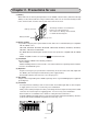
Chapter 2. Precautions for use (1) Battery When delivered, the memory backup batteries in the JW300 control modules (JW-311CU through 362CU) are disconnected. Before using a control module, make sure to connect the battery module to the control module, clear the memory and set the time for the clock. - The battery module is stored under the battery cover when delivered. - See section 8-3. "Battery" in this manual, for details about battery life.
(7) Wiring - Be aware not to confuse the connection polarity of 5 VDC on the expansion rack panel. Otherwise, rack panel and I/O module etc. may be damaged. - Keep the input/output lines away from high voltage or strong current lines such as power lines. (8) Cautions for static electricity Significant volume of static electricity may build up on the human body in extremely dry conditions. Prior to touching the JW300, discharge the static electricity by touching grounded metals.
Chapter 3. System configuration 3-1 Basic system configuration Expansion rack panel (The number of modules that can be connected: Maximum 7) I/O bus expansion adapter* (JW-32EA) Terminal connector (Attached to JW-31EA) I/O / special I/O module I/O expansion cable (Total length: max.
■ The difference between using and not using I/O bus expansion adapter JW-31EA/32EA When not using I/O bus expansion adapter When using I/O bus expansion adapter JW-32EA I/O bus expansion adapter → 32 E A Rack 6 32 E A Rack 5 32 E A Rack 4 32 E A Rack 3 Rack 3 32 E A Rack 2 Rack 2 32 E A Rack 1 Rack 1 32 E A Rack 0 31 E A Expansion rack panel System configuration Expansion rack panel Basic rack panel Basic rack panel Rack 0 → Rack 7 JW-31EA I/O bus expansion adapter Basic rack pan
(1) Control module Model mame Program capacity File register capacity Memory card I/F JW-311CU 8K words - None JW-312CU 8K words - Yes JW-321CU 16K words 32K bytes None JW-322CU 16K words 32K bytes Yes JW-331CU 32K words 128K bytes None JW-332CU 32K words 128K bytes Yes JW-341CU 64K words 512K bytes None JW-342CU 64K words 512K bytes Yes JW-352CU 128K words 2048K bytes Yes JW-362CU 256K words 8192K bytes Yes No.
(6) I/O / special I/O / option / device net / I/O link module Model name JW-203N Specifications 8 points input, 200/240 VAC JW-211NA 16 points input, 100/120 VAC JW-212NA 16 points input, 12/24 VDC JW-214NA 16 points input, 12/24 VDC (high speed type) I/O JW-234N 32 points input, 12/24 VDC (high speed type, connector connection) JW-204SA 8 points output, 250 VAC/30 VDC, 2 A relay output (separated common) JW-212SA 16 points output, 5/12/24 VDC, 0.
(7) I/O expansion cable Model name JW-203EC JW-207EC JW-22EC JW-25EC JW-210EC JW-05EC JW-1EC JW-3EC JW-10EC JW-20EC JW-30EC JW-50EC Specifications Connection cables between a basic rack panel and an expansion rack panel, or between expansion rack panels. Connection cables between a JW-31EA and a JW-32EA, or between a JW-32EA and a JW-32EA.
3-2 System configuration using communication For details of the communication modules (option / device net / I/O link modules), refer to the each module user’s manual. When using the optional modules listed below, make sure that the ones you select are compatible with the JW300 series. JW-21CM, JW-22CM, JW-21MN, JW-255CM, JW-25TCM, JW-20FL5, JW-20FLT, JW-22FL5, JW22FLT, JW-22SU, JW-25CM. - The JW300 will not work with option modules that are not specified as compatible with the JW300 series.
[2] Communication system using link module (JW-21CM) - The JW-21CM can use any of the following 4 functions by setting its internal switch.
(2) Data-link DL1 - This communication system can change data between a master and a slave station, or between 2 slave stations, with a PLC configuration that uses the JW-21CM as a master station or a slave station. (N:M method) JW-340CU JW-340CU CM1 ON RUN ↑ FLT PROTECT JW70H JW300 JW300 CM2 JW-10CM (slave) JW-21CM (slave) JW-21CM (slave) CM1 ON RUN ↑ CM2 FLT PROTECT USB USB Slave station: 15 sets max.
(4) Remote I/O master station - The system can communicate between a JW-21CM as remote I/O master station and remote I/O slave station. JW-21CM (Master station) JW-21RS (slave) JW-21RS (slave) JW-21RS (slave) JW-21RS (slave) JW300 JW-340CU CM1 ON RUN ↑ CM2 FLT PROTECT USB ▲ PULL PG/COMM1 電池交換 時期 This battery expires 電池の交換 は5分以内 に行ってく ださい Exchange the battery within 5minutes. PG/COMM2 Shielded-twist pair cable Total length max. 500 m Item 307.2 kbits/s Slave station 4 sets max.
[3] Communication system using the satellite module (JW-22CM) The system can communicate between PLCs or between personal computers by mounting a JW-22CM on a JW300. - It can realize data linking (N:M method) and computer linking on the same communication line. - The JW-22CM is an option module, and up to 7 modules (including other option modules) can be mounted only to a basic rack panel.
[5] Communication system using the Ethernet (JW-255CM/25TCM) Install the JW-255CM/25TM on the JW30H, and connect it to a transceiver using a transceiver cable, you can exchange data with a host computer or any LAN system in the network, on the Ethernet *1. - Both TCP/IP and UDP/IP protocols are available. - Data communication is possible between host computers in an Ethernet network and PCs in a satellite network or on an FL-net spanning two layers of hierarchy.
[6] Communication system using FL-net (JW-20FL5/T, JW-22FL5/T) The JW-20FL5/22FL5 (for 10BASE5) and JW-20FLT/22FLT (for 10BASE-T) are modules for the "FLnet" *1 next generation control system network. They facilitate connection with different devices such as NC and industrial robot as well as other manufacturers’ PLCs. - Join to a network is simple by a node automatic entrance and removal function.
■ FL-net specifications Specifications Item JW-20FL5, JW-20FLT JW-22FL5, JW-22FLT Ver. 1 Applicable version Ver. 2 Communication control method Masterless, token system Number of connecting stations Maximum 254 Communication function Cyclic data transfer (n: n, 8 k-bits + 8 K-words) Message transfer (1:1, 1: n) Maximum data length of one frame: 1 K-bytes [7] Communication system using the JW-20DN DeviceNet The JW-20DN conforms to the DeviceNet * and can connect various slave stations.
Items Specifications Communication protocol Device net or equivalent Basic operation mode Master mode, slave mode No. of connectable nodes A maximum of 63 slave nodes can be connected to one master node. Max. 4096 points (Max.
[8] Communication system using the satellite I/O link (JW-23LMH) The system can communicate between a JW-23LMH as an I/O link master station and an I/O link slave module. Up to 4 JW-23LMH modules can be mounted only on a basic rack panel. JW-23LMH (master station) JW300 JW-340CU CM1 ON RUN ↑ CM2 FLT PROTECT (slave) 8-point module (slave) (slave) 16-point module 32-point module (Slave station) LCD control terminal, manifold solenoid valve, etc.
[9] Communication system using a JW10 link module (JW-25CM) The JW-25CM can communicate with the JW10, by selecting data link master station function or remote I/O master station function. The JW-25CM is an option module, and up to 7 modules of JW-25CM (including other option modules) can be mounted only to a basic rack panel. (1) Data link master station The system can communicate between a JW-25CM, a master station, and a JW10, slave station.
(2) Remote I/O master station The system can communicate between a JW-25CM as a remote I/O master station and a JW10 basic module as a remote I/O slave station. - Whether or not to synchronize a data exchange between a master and a slave station with operation can be selected. JW-25CM (master station) JW300 JW-340CU CM1 ON RUN ↑ CM2 FLT PROTECT JW10 (slave) JW-25CM USB JW10 (slave) JW10 (slave) UNIT NO.
3-3 System design procedures The following is an example of the system design procedure of the JW300. Start System design Select of memory capacity (model of control module) and set up number of I/O module etc.
3-4 Precautions for system design If an error occurs in the PLC, the whole system will report a fault. In order to create a fail-safe system, we recommend preparing independent external protective circuits for following functions, which may cause a breakdown of machine or injury to workers: • Emergency stop circuit, • Protection circuit, • Operating circuit of high voltage device. Also, be aware of the operation response time, as a PLC operates using cyclic processing.
(2) In case of using DC power supply (24 VDC) • Connecting an input module and output module for lighting lamps in front of emergency stop circuit makes it possible to grasp the stop condition of devices. 0V JW300 Input module • When the JW300 stops its operation, all the output module indicate ON/OFF condition just before stopping. Note: When setting an output holding address in the system memory, all the output after the setting address is retained and you can reset the previously set address.
Chapter 4. Name and function of each part 4-1 Control module (JW-3**CU) Model name label (8) (1) (9) ← O F F (14) PROTECT AUTO LD RESET Module retention screw (1pc.) (2) (3) RUN FLT CM1 CM2 C A R D (10) (4) (5) USB MW (7) Rating plate (6) (11) (12) (15) (16) ▲ PULL PG/COMM1 電池交換 時期 This battery expires (17) Software version label 電池の交換 は5分以内 に行ってく ださい Exchange the battery within 5minutes.
Name Function (10) RESET switch Software reset - If the calculation time for one scan is abnormally long, the JW300 may repeat a run and stop sequence. In this case, press the RESET switch to change the JW300 to the program mode. (11) USB port * A connector used to connect the JW300 to a USB port on a personal computer. (USB1.1 compatible.) (12) PG/COMM1 port * A connector for connecting with device having Serial I/O port such as (RS-232C / RS-422A) support tool, personal computer.
4-2 Power supply module The power supply modules that can be used with the JW300 are as follows: Model name Specification Approved Approved UL CSA JW-303PU *1 85 to 264 VAC. Power capacity: 5 VDC 4.5 A JW-301PU *2 85 to 264 VAC. Power capacity: 5 VDC 3.5 A JW-31PU 85 to 132 VAC. Power capacity: 5 VDC 3.5 A JW-22PU 20.4 to 32 VDC. Power capacity: 5 VDC 3.5 A O O *1: The JW-33PU power supply module for theJW20H/30H can also be used with the JW300.
[Power supply terminal block] This is a terminal block for connecting extended line of power supply, GND, halt output and the like. JW-301PU *1 L POWER INPUT 100-240 VAC N POWER RUN *5 Short bar 85 to 264 VAC Power supply input terminal *2 GND (grounding) terminal SHORT GND HALT OUTPUT 100-240 VAC (24 VDC) 1A JW-31PU JW-22PU (+) POWER INPUT 24 VDC *1 L POWER INPUT 100-120 VAC N *5 Short bar SHORT *4 20.
[2] JW-303PU POWER lamp (green) (Lights when power is supplied) RUN lamp (green) - Operating normally, lights ON - Programming after connecting support tool : Blinking (PLC stops operation) - Detect errors by self-diagnosis function : Lights OFF (when battery is error, lights ON.) Module retention screw JW-303PU POWER RUN 増設ベースユニット EXPANSION RACK PANEL Programmer retention screw hole Rack number label Write rack number of expansion rack panel. Module insert guide Rating plate RACK NO.
4-3 Input/output module The input/output module can be installed in any order in the I/O module slot of the basic/expansion rack panel. ■ Kinds of input/output module I/O modules having 8, 16, and 32 points are available. Special I/O modules having 64 points are available.
[1] 8/16 points module Current consumption mark Module name label A Input/output signal indication lamp Lights when input/output signal "ON" 0 1 2 3 4 5 6 7 B 0 1 2 3 4 5 6 7 Indications the current consumption of 5 VDC input/output module. (One label: Approx. 100 mA) Terminal block retention screw Module retention screw Connector Connects with connector for the I/O slot of basic/ expansion rack panel. Input/output terminal block Connects external lines of input/output devices.
[2] 32 points module Current consumption mark Module name label A Input/output signal indication lamp 0 1 2 3 4 5 6 7 B 0 1 2 3 4 5 6 7 C Module retention screw Indication of the current consumption of 5 VDC in input/output module. (One label: Approx. 100 mA) Connector 0 1 2 3 4 5 6 7 D 0 1 2 3 4 5 6 7 Lights when input/output signal is "ON" Connects with connector for the I/O slot of basic/ expansion rack panel.
[3] 64 points module Current consumption mark Module retention screw Fuse LED *1 (Only JW-262S) Module No. switch Module name indication label 01234567 Input/output signal indication lamp Indicating lamp selector switch A B C D Module insert guide Connector FUSE 2 UNIT NO.
4-4 Basic/expansion rack panel [1] Basic rack panel Three types of basic rack panels are provided, with variations in the number of slots available for connecting I/O modules. Number of slots Model name For power supply module For control module For I/O module JW-314KB 1 1 4 JW-316KB 1 1 6 JW-318KB 1 1 8 In the slot for I/O module, I/O, special I/O, I/O link, and option module, device net, and I/O link can be connected in mixture.
[2] Expansion rack panel Three types of expansion rack panels are provided, with variations in the number of slots available for connecting I/O modules. Model name No. of slot For power supply module For I/O module JW-34ZB 1 4 JW-36ZB 1 6 JW-38ZB 1 8 In the slot for I/O module, I/O and special I/O module can be connected in mixture. The option, device net, and I/O link module cannot be installed on it.
[3] Rack No. (expansion rack panel) (1) In case of not using I/O bus expansion adapter System can be configured with up to 4 racks, and each rack ID number will be specified by the settings of the rack number switch on the expansion rack panel(JW-34ZB/36ZB/38ZB). The basic rack panel is fixed to rack No. 0. Rack No. switch Rack No. 3 123 Rack No. 2 123 Rack No.
(2) In case of using I/O bus expansion adapter System can be configured with max. 8 racks when an expansion rack panel, JW-34ZB/36ZB/ 38ZB, is connected with an I/O bus expansion adapter, JW-32EA. Each rack panel ID number will be defined by combination of settings for the rack number switches on the expansion rack panel and the JW-32EA. The basic rack panel is fixed to rack No. 0. Rack No. switch of expansion rack panel Rack No. Rack No. switch of I/O bus expansion adapter (JW-32EA) 1 ON for only No.
(3) Setting example for rack No. I/O bus expansion adapter (JW-32EA) Rack No. switch Expansion rack panel Rack No. switch 4-7 123 Rack No. 7 Termination connector 4-7 123 Rack No. 6 1-3 4-7 123 Rack No. 5 1-3 4-7 123 Rack No. 4 1-3 4-7 123 Rack No. 3 1-3 4-7 123 Rack No. 2 1-3 4-7 123 Rack No.
[4] Important points when using basic /expansion rack panels System specifications can be defined by the combination of basic rack panel and expansion rack panel as shown in the table below.
4-5 I/O bus expansion adapter I/O bus expansion adapter for the JW30H has two available models, the JW-31EA and the JW-32EA, that are used to link signals sent from each rack panel. The JW-31EA is installed in the basic rack panel JW-314KB/316KB/318KB, while the JW-32EA is installed in the expansion rack panel JW-34ZB/ 36ZB/38ZB. The I/O expansion cable, JW-05EC/1EC/3EC/10EC/20EC/30EC/50EC, is used to connect rack panels (install the I/O bus expansion adapter).
[1] JW-31EA Module fixing screw (1) Rating plate Module fixing screw (1) I/O expansion connector Connect between the I/O expansion connectors (IN) of JW-32EA using I/O expansion cables. [2] JW-32EA Module fixing screw (1) (2) (3) Rating plate (4) (5) Module fixing screw (1) Connector for support tool connection (EA-PG port) Connecting a support tool (JW-300SP, JW-15PG), such as a hand-held programmer, enables creating/changing/monitoring program on the expansion rack panel that is max. 50 meters away.
Notes - Only one support tool (JW-300SP, JW-15PG) can be connected to the JW-32EA. [Ex.] Control module JW-31EA JW-32EA JW-32EA Support tool Support tool - With the JW300 system, while a support tool (JW-300SP, JW-15PG) is connected to the control module, another support tool can be connected to the JW-32EA. (The JW30H cannot connect to a support tool under this condition.) [Ex.
[3] 64 points module Current consumption mark Module retention screw Fuse LED *1 (Only JW-262S) Module No. switch Module name indication label 01234567 Input/output signal indication lamp Indicating lamp selector switch A B C D Module insert guide Connector FUSE 2 UNIT NO.
4-4 Basic/expansion rack panel [1] Basic rack panel Three types of basic rack panels are provided, with variations in the number of slots available for connecting I/O modules. Number of slots Model name For power supply module For control module For I/O module JW-314KB 1 1 4 JW-316KB 1 1 6 JW-318KB 1 1 8 In the slot for I/O module, I/O, special I/O, I/O link, and option module, device net, and I/O link can be connected in mixture.
[2] Expansion rack panel Three types of expansion rack panels are provided, with variations in the number of slots available for connecting I/O modules. Model name No. of slot For power supply module For I/O module JW-34ZB 1 4 JW-36ZB 1 6 JW-38ZB 1 8 In the slot for I/O module, I/O and special I/O module can be connected in mixture. The option, device net, and I/O link module cannot be installed on it.
[3] Rack No. (expansion rack panel) (1) In case of not using I/O bus expansion adapter System can be configured with up to 4 racks, and each rack ID number will be specified by the settings of the rack number switch on the expansion rack panel(JW-34ZB/36ZB/38ZB). The basic rack panel is fixed to rack No. 0. Rack No. switch Rack No. 3 123 Rack No. 2 123 Rack No.
(2) In case of using I/O bus expansion adapter System can be configured with max. 8 racks when an expansion rack panel, JW-34ZB/36ZB/ 38ZB, is connected with an I/O bus expansion adapter, JW-32EA. Each rack panel ID number will be defined by combination of settings for the rack number switches on the expansion rack panel and the JW-32EA. The basic rack panel is fixed to rack No. 0. Rack No. switch of expansion rack panel Rack No. Rack No. switch of I/O bus expansion adapter (JW-32EA) 1 ON for only No.
(3) Setting example for rack No. I/O bus expansion adapter (JW-32EA) Rack No. switch Expansion rack panel Rack No. switch 4-7 123 Rack No. 7 4-7 123 Rack No. 5 4-7 1-3 1-3 4-7 123 Rack No. 4 1-3 4-7 123 Rack No. 3 1-3 4-7 123 Rack No. 2 1-3 4-7 123 Rack No. 1 1-3 123 Rack No.
[4] Important points when using basic /expansion rack panels System specifications can be defined by the combination of basic rack panel and expansion rack panel as shown in the table below.
4-5 I/O bus expansion adapter I/O bus expansion adapter for the JW30H has two available models, the JW-31EA and the JW-32EA, that are used to link signals sent from each rack panel. The JW-31EA is installed in the basic rack panel JW-314KB/316KB/318KB, while the JW-32EA is installed in the expansion rack panel JW-34ZB/ 36ZB/38ZB. The I/O expansion cable, JW-05EC/1EC/3EC/10EC/20EC/30EC/50EC, is used to connect rack panels (install the I/O bus expansion adapter).
[1] JW-31EA Module fixing screw (1) Rating plate Module fixing screw (1) I/O expansion connector Connect between the I/O expansion connectors (IN) of JW-32EA using I/O expansion cables. [2] JW-32EA Module fixing screw (1) (2) (3) Rating plate (4) (5) Module fixing screw (1) Connector for support tool connection (EA-PG port) Connecting a support tool (JW-300SP, JW-15PG), such as a hand-held programmer, enables creating/changing/monitoring program on the expansion rack panel that is max. 50 meters away.
Notes - Only one support tool (JW-300SP, JW-15PG) can be connected to the JW-32EA. [Ex.] Control module JW-31EA JW-32EA JW-32EA Support tool Support tool - With the JW300 system, while a support tool (JW-300SP, JW-15PG) is connected to the control module, another support tool can be connected to the JW-32EA. (The JW30H cannot connect to a support tool under this condition.) [Ex.
Chapter 5. Installation 5-1 Precautions for installation The JW300 is not designed for dust and waterproof construction. Therefore, install JW300 in an enclosed panel. Avoid keeping the JW300 in the following conditions: 1. Ambient temperature extremes outside the range of 0 to 55 °C 2. The relative humidity exceeding the range of 35 to 90% 3. Sudden temperature changes, which may cause condensation. 4. Corrosive and flammable gases. 5. Water, oil and organic solvents dripping positions. 6.
5-2 Installation of basic/expansion rack panel This section explains the installation method of the basic/expansion rack panel in a control panel. Fix the basic/expansion rack panel on a partition plate of a control box. Select the appropriate fixing place taking into consideration the size of a wiring duct, wiring to the JW300, a cable length of the I/O expansion cable, ventilation, maintenance, easy access for exchanging modules etc.
[2] Installation of basic/expansion rack panel in control panel 1) Drill fitting holes of basic/expansion rack panel and wiring duct on the control panel and partition plate. - Refer to previous page for fitting dimension of the basic/expansion rack panel. - Keep each rack panel at 50 to 150 mm distance and more, from right and left sides of each rack panel to the end of the panel and the wiring duct for 50 mm and more.
From the previous page 3) Fit wiring duct - Prepare the retention screws locally. - Use a wiring duct to enable easy external wiring for the I/O / special I/O / option / device net / I/O link module of the JW300. By installing a mounting base and increasing the wiring duct height to the same level as the JW300, it will be easier to install the cables and make the necessary connections. 4) Set the rack no. switch of expansion rack panel. - See page 4-11 to 13 for setting a rack no. switch.
5-3 Installation of power supply module Power supply module JW-303PU/301PU/31PU/33PU are installed by basic/expansion rack panel. Be sure to install the power supply module on the basic rack panel. Total consumption current of the power supply module is 3.5 A or less when JW-301PU/31PU/22PU is used, and 4.5 A or less when JW303PU is used. (See page 7-1 to 3) Install a power supply module in any of the cases below: 1. When the total consumption current of the power supply module exceeds 3.
5-4 Installation of control module Install the control module (JW-3**CU) at the basic rack panel (the power supply module on the right.) [Installation procedure] 1) First, catch the module securing rib in a securing rib hole on the basic rack panel. Then, push the module in toward the basic rack panel.
5-5 Installation of I/O / special I/O / option module I/O modules and special I/O modules can be installed in a basic rack panel or expansion rack panel. The option, device net, and I/O link modules can only be installed in a basic rack panel. Mixed installation of these modules in the same rack panel is possible. - When setting up the system, arrange so that the total of the current consumptions of each module may be within the output current of the 5 VDC power source supplied from the power supply module.
[2] Installation of module cover Module cover JW-20CV is a cover fitted on a terminal block of the I/O / special I/O / option / I/O link module to which external cables are connected. Module covers are ordered separately (8 sets in one pack.) [Installation procedure] 1) Put the external lines connected to the I/O / special I/O / option / I/O link module into the portion reserved for storage portion.
5-6 Installation of I/O bus expansion adapter (JW-31EA/32EA) Install JW-31EA on an I/O expansion connector on the right edge of the basic rack panel, JW-314KB, etc. Install JW-32EA on an I/O expansion connector on the right edge of the expansion rack panel, JW34ZB, etc. [Installation procedure] 1) Insert a termination connector, which is an accessory of the JW-31EA, into the JW-32EA only on the last expansion rack panel.
Chapter 6. Wiring 6-1 Precaution for wiring Follow the below instructions for wiring: 1. Separate power line and I/O lines of the JW300 from high voltage lines and power lines as far as possible. Do not run power lines and I/O lines in parallel with high voltage or power lines. 2. For the I/O expansion cable and wiring the 5 VDC lines, use supplied accessories for the I/O expansion cable. 3. Don't run the I/O expansion cable and the 5 VDC cable inside a duct. 4.
■ Wiring with noise countermeasures For your safe usage of the JW300, observe the "Precaution for Wiring" of the previous page carefully. Wiring to prevent the JW300 from malfunction caused by noise is shown below. Besides, some malfunctions by noise come from complex causes or a cause, which cannot be analyzed in quantity. Use the following noise countermeasures as your reference, when you take measures for each actual situation.
Note: Observe the following points for direct grounding of the GND cable of the JW300 to the chassis: - Connect the grounding cable from the GND terminal of the power supply module of JW300 to the chassis in the minimum distance. The same wiring manner should be used for the expansion rack panel. Power supply module Basic rack panel Ground cable Ground Connect the grounding cable to the fastening screw on the rack panel.
(2) Countermeasure of noise from power supply line The AC power supply input noise resistance capacity of the JW300 is 1000 Vp-p. When any noise over this limit is possible to come through the power supply line, install an insulation transformer. Countermeasure: Install an insulation transformer Noise has a high frequency of 100 KHz to 2 MHz, which should be blocked by a transformer.
(3) Safeguard from lightning Below are countermeasures in case when the factory facilities are located far from residential areas and that effects from induced lightning (induced voltage by lightning strikes) are expected. Note, however, that they are not the measures for direct strikes of lightning. In some cases, the voltage of the induced lightning may go beyond 4000 KV. Therefore, the purpose of these countermeasure is just to minimize the damage on the device.
Countermeasure 2: Underground wiring as a countermeasure of lightning. When communication cables and input cables of the JW300 go out of a building, place them underground. Provide junction for input/output signals using relays. 1. Underground cabling In a lightning weather condition, the atmosphere is electrically charged and a wiring in the air induces a voltage of over 24 VDC. Therefore, place the wiring under the ground.
(5) Note for external wiring to I/O module 1. Relay output module: JW-204SA, JW-214SA Since the relay output module does not have a built-in surge absorbing circuit, do not forget to install a surge killer, such as a varistor, in the output side. Operation without a surge killer might give bad effects on other modules by spark noises from the relay. As for the surge killer, see page 7-16 "Precautions for operating I/O module." 2.
4. Wiring with power line Do not run the input signal, output signal and communication cables of the JW300 near and in parallel with the power line. - When input and output signal cables are extended over 100 m, make separate wiring for the input signal and the output signal of JW300. Input Output PLC Separate wiring Input Output When longer than 100m - Make separate wiring for the input signal and the output signal of the JW300 from the power line.
6-2 Wiring communication ports The relationship between the control module, communication ports, and communication standard are as follows: Comunication port (communication standard) Control module PG/COMM1 port (RS-422A/RS-232C) PG/COMM2 port (RS-422A/RS-232C) JW-311CU/312CU Yes No Yes Yes EA-PG port *1 (RS-422A) JW-321CU/322CU JW-331CU/332CU JW-341CU/342CU Usable JW-352CU/362CU *1: The EA-PG port is a port on the JW-32EA I/O bus expansion adapter.
- EA-PG port 1514131211 10 9 8 7 6 5 4 3 2 1 JW-32EA (15 pin D-sub female connector) Pin No.
[2] Wiring figure (1) When using RS-232C for communication method of host computer side Be within 15m for the total length of a communication cable. JW-3**CU (PG/COMM1 port) Host computer Shielded wire Pin No. Signal name Signal name 1 FG FG 2 SD RD 4 RD TD 7 SG SG JW-3**CU (PG/COMM2 port) Within 15 m RS-232C Host computer Shielded wire Pin No.
(2) When using RS-422A for communication method Be within 1km for the total length of a communication cable. - JW-3**CU PG/COMM1 port or PG/COMM2 port - JW-32EA (EA-PG port) - JW-3**CU PG/COMM1 port or PG/COMM2 port - JW-32EA (EA-PG port) Host computer Pin No. Signal name Pin No.
6-3 Wiring for power supply module In order to prevent wire wastes from dropping into the module through a ventilation hole of the power supply module (JW-303PU, etc.) during the wiring work, keep the caution label stuck onto the upper side of the module. Peel the caution label off of the module when all wiring work is finished. A cover was installed on the terminal block of the power supply module at delivery.
(2) JW-22PU (DC power supply module) + POWER RUN DC power supply (20.4 to 32V) − Halt output Be sure to connect the line to the emergency stop circuit. Ground line To prevent electric shock and noise error, be sure to separately prepare class-D ground. - Ensure correct connection for polarity of the input power supply. Mis-connection of the polarity will destroy the module when power is supplied. - As for DC input power supply, use power supply of 20.
6-4 Wiring to I/O module Before wiring to the I/O module confirm the specifications of the module. If the module is used beyond its rated specifications, the module might be damaged, destroyed or cause fire. Wiring to the I/O module, use a twisted wire of over KIV 0.5 square (over KIV 0.75 square in case of wiring to the output module of large capacity, such as solenoid valves) and crimp-style terminals. For the common line, use bigger wires than the above.
[2] Connector type of 32/64 points (1) Assembly of the connector Assemble the connector following the procedures below. Note that the terminal numbers of the connector are not identical with address numbers. 1) Insert insulation tube into signal line. Soldering Insert a tube Jack 2) Solder signal line to connector terminal. Confirm the connector terminal and its address number, before soldering. 3) Assemble connector. Assembly parts (screws, washers and nuts) are attached to the connector.
Wiring Model name Manufacturer Remarks Need a pressure welding tool. Flat cable 1.27 mm pitch Recommended our AWG28 (twisted wire) crimp-style of tool AWG30 (single wire) made by FUJITSU CO., LTD.*1 Pressure FCN-367J040-AU/F welding (Connector) FCN-360C040-B (Connector cover) FCN-363J040 Crimp-style (Housing) FCN-363J-AU (Contact) FCN-360C040-B (Connector cover) Soldering FCN-361J040-AU (Connector) Recommended wiring size FUJITSU CO., AWG24 to AWG28 LTD Strip outer of cable is Ø1.
6-5 Wiring to basic/expansion rack panel [1] Installation of I/O expansion cable (1) Install basic/expansion rack panel in direct Connects between the basic rack panel and the expansion rack panel, or between the expansion rack panel and another expansion rack panel using following cables. (Max.
(2) When installing in an I/O bus expansion adapter Connect an I/O bus expansion adapter, JW-31EA (mounted on a basic rack panel), to a JW-32EA (installed in an expansion rack panel), or between two JW-32EAs using one of the following cable assemblies. (Max. 8 racks can be connected).
[2] Wiring for 5 VDC cable, process of panel wiring Be sure to supply 5 VDC to the expansion rack panel without power supply module, through the 5 VDC terminal block of the basic/expansion rack panel with power supply module. Without a supply of 5 VDC power supply, the I/O module cannot run. - Be careful not to mistake polarity in connection of basic/expansion rack panel into the 5 VDC terminal block. Mis-connections might damage the module or cause fire.
(2) Wiring processing example of eight rack systems Wiring duct Wiring duct 5 VDC cable Wiring duct AC/DC power supply ▲ Halt output Wiring duct Termination connector Class-D grounding 6-21
Chapter 7. Directions for use 7-1 Current consumption of module Each module in the JW300 operates by 5 VDC output current supplied by the power supply module: JW301PU, etc. The make up the system configuration plan is such that the total current consumption of each module does not exceed the current capacity of the power supply module. When the total current consumption of each module exceeds the supply capacity, the JW300 stops operation by the current limit function of the power supply module.
4) Input/output / special I/O / option / device net / I/O link module Current consumption : mA (when all points ON) No.
(2) Calculation of current consumption (by current consumption mark) Add up the total numbers of the current consumption mark on stickers next to the model name label. One mark of current consumption means approx.100 mA. Constitute a system in order to follow the below conditions: Conditions: The total current consumption units, as shown by stickers on the modules receiving power, must not exceed 35 when the JW-301PU, JW-22PU or JW-31PU are used as the power supply module.
7-2 How to calculate the heat value (average power consumption) of the JW300 when designing panels. Obtain the average power consumption of the entire JW300 system following the calculations below, and calculate temperature inside a panel. 1) Power supply module. Wpw = 3 7 x (I5V x 5) (W) I5V: Current consumption of 5 VDC circuit of respective module. 2) Tatal comsumption electric power of respective module.
7-3 Allocation of relay numbers Relay numbers for the input, output, special, and option modules are stored in the control module of the JW300 system for each rack and each slot, depending on the type of modules installed. There are two method to register relay numbers: 1) Automatic I/O registration by turning ON the power to the modules (does not need any support tool), 2) Manually enter I/O addresses using a support tool.
(1) Auto registration The control modules automatically register I/O addresses, using sequential addresses starting from " コ00000," in the same order as the rack numbers (0 to 7). Rack No. 3 Rack No. 7 Rack No. 2 Rack No. 6 Rack No. 1 Rack No. 5 コ0000 Rack No. 0 Rack No. 4 - In the example above, the rack numbers are listed in order installed. - Number of I/O points and I/O relay area. Shown below are examples using basic rack panel (JW-318KB) and 7 expansion rack panels (JW38ZB.) No.
(2) Free I/O registration (continuous allocation) Specify the top address for each rack (0 to 7), within the range of コ00000 to コ01577. I/O addresses are registered continuously, starting from the specified top address, on each rack. Set the top address Set the top address Rack No. 3 Rack No. 7 Set the top address Set the top address Rack No. 2 Rack No. 6 Set the top address Set the top address Rack No. 1 Rack No. 5 Set the top address Set the top address コ0000 Rack No. 0 Rack No.
(3) Free I/O registration (individual allocation) Specify the top address for each rack (0 to 7), within the range of コ00000 to コ01577. I/O addresses are registered continuously, starting from the specified top address, on each rack. Set the top address Set the top address Rack No. 7 Rack No. 3 Set the top address Set the top address Rack No. 2 Rack No. 6 Set the top address Set the top address Rack No. 1 Rack No. 5 Set the top address Set the top address Rack No. 0 Rack No.
[2] I/O relays allocated to each module Relay numbers in each rack panel are automatically allocated in series following each rack top address set by I/O register. Number of points and contents of relays allocated varies with kinds of module. Kind of module 8 points input module Allocation No. of points 16 8 points output module Contents of allocated relay No. Instead of 8 points, 16 points are assigned.
[3] Number of input/output points and allocation of input/output relays The number of I/O points (control) and the number of I/O relay allocation points are as follows: The number of relays will vary, depending on the type of module. ■ Number of control input/output points and allocation of input/output relays Control module Number of I/O points (control) Number of I/O relay allocation points JW-311CU/312CU Max. 512 points Max. 1280 points JW-321CU/322CU Max.
- Module installation examples Below shows an installation example when one set of the JW-318KB basic rack panel (8 slots) and 7 sets of the JW-38ZB expansion rack panels (8 slots) are used.
[4] Allocation example of relay no. (1) Example of auto I/O registration This is to show the relay numbers in the following system configuration. 000220 000240 000260 000300 000320 000360 000400 000420 Rack No.
7-4 Data memory for special I/O, option, device net, I/O link, and option module Data memory for use special I/O module is set by module No. switch of each modules.
Remark Setting value of the module No. switch * When setting the module No. switch on a special I/O module, option module, device net module, or I/O link module, note the following carefully: 1) Do not use the same module switch setting on two or more of the following module types in the same system. 1. Option modules 2. Device net modules 3. I/O link modules 4. Device net modules and I/O link modules 2) Do not use the same module switch setting for special I/O modules on the same rack panel.
[1] Data memory for special I/O module The special I/O module will be assigned a place in the special I/O module relay area and the special I/ O parameter area by the setting of the Module No. switch (0 to 7) on the special I/O module. Max.8 sets Setting value of module No. switch Rack No.7 JW-38ZB Max.8 sets Rack 7 Rack No.6 JW-38ZB Max.8 sets Rack 6 Rack No.5 JW-38ZB Max.8 sets Rack No.4 JW-38ZB Rack 5 Max.8 sets Rack No.3 JW-38ZB Rack 4 Max.8 sets Rack No.2 JW-38ZB Rack 3 Max.
■ In case of remote I/O system using JW-21CM link module A maximum of 8 special I/O modules can be installed in the JW-21RS remote I/O slave station. The special I/O module will be assigned a place in the special I/O module relay area and the special I/O parameter area by the setting of the Module No. switch (0 to 7) on the special I/O module. Relay area for special I/O module Set value of module No. switch ● Example of system Max.8 sets Rack No.2 JW-38ZB Max.
7-5 Precautions for operating I/O module [1] Precautions for operating input module (1) ON/OFF time of the input signal In order to ensure ON/OFF condition of the input device correctly (limit switch etc.) on the operation of the JW300, ON or OFF time should meet the following conditions.
(2) Connectable input device The followings are sensors and switches, which can be connected as input. See below for selection and connection of the input device.
(3) Countermeasure leakage current on input device In the following device, there is also leakage current at OFF. If the leakage current is higher than the OFF level of the input module, the input module may not turn OFF, or noise margin at OFF state may drop.
Countermeasure:Connection of bleeder resistance As a countermeasure, a bleeder resistance can be inserted in the input side of the input module as shown below.
(4) Notes for long-distance wiring and by-pass wiring In the AC input module, when the cables to external device are very long or wiring along with power lines is made, the input module might be turned ON in spite of the OFF command in the input device, due to leakage current and inducement by floating capacity among cables. Input module IN COM Power line, etc.
(5) Surge current of the AC input module There is surge current in the AC input module: JW-203N/211NA, when turning ON the input. The surge current of the AC input module is determined by constants (R, C) of the input circuit inside the module, power supply voltage at ON input, phase, power supply current capacity and wiring impedance. The surge current stated in the AC input module specifications is the worst value for the case of the ON input at the maximum impressed voltage and at the peak phase.
[2] Precautions for operating the output module (1) Protection from output short circuit In case of a short circuit of the load connected to an output terminal, output devices and print board may be burned. Be sure to insert a protection fuse in the output. Some modules have a built-in fuse per common line for protection of the module from heating and burning due to excessive current.
(3) Countermeasure to surge voltage at opening/closing induced load Some load generates surge voltage of several thousands volt when an induced load is operated or closed its circuit. All output module except the relay output module have a circuit to absorb surge within module. However, when the wiring to the load is long, its effectiveness is reduced and a surge countermeasure is required in the load side as well.
Note: Avoid the use of a capacitor only as an arc killer, as shown below: C 7-25 Load Power supply Power supply Load Though a capacitor is very effective for the arc deletion at shut-off. But charged current to the capacitor may melt the contact point at turning ON a contact point. C Though a capacitor is very effective for the arc deletion at shut-off. But at the opening of the circuit of a contact point, electricity is accumulated at the capacitor.
(4) Load which can be driven by the AC output module The AC output module with SSR as an output device JW-213SA can drive directly the loads of electro-magnetic switches, solenoid valves and lamps. In such cases note the surge current at turning ON (from OFF to ON) and the maintenance current during the maintenance state (ON state).
Calculate the value R of the bleeder resistance in the following formula: R< V I V: Power supply voltage I: Minimum action current of the output module Then, the capacity of R (W) is W> V2 ×3 R Margin (5) OFF delay time when the DC output module drives the induced load When the DC output module with a built-in cramp diode is used as a surge killer to drive the induced load of direct current such as electro-magnetic valves and solenoid valves, it may be impossible to complete high-speed switching due t
(7) Life of relays of the relay output module The relay's life of the module (JW-204SA/214SA), which uses a relay in output circuit, varies depending on the kind of loads (difference of the power rate of the signal on the contact point is AC or DC and its current value). The following shows characteristic curves of the relay contact point. Max. 2,000,000 times No. of switching (x 10,000 times) 200 100 70 30 VDC T = 0 50 120 VAC COSφ=1 30 250 VAC COSφ=1 10 30 VDC T = 7 ms 7 120 VAC COSφ= 0.
7-6 Computer link using communication port The PG/COMM1 and PG/COMM2 ports are built into the JW-3**CU control module as communication ports for the JW300 series. The EA-PG port is available on the JW-32EA I/O bus expansion adapter. You use communication ports to communicate with host computers (personal computers, LCD control terminals, etc.) through the RS-232C/422A I/O ports. - They can communicate using the same method as the SHARP computer link.
■ EA-PG port Expansion rack panel I/O bus expansion adapter (JW-32EA) Personal computer, etc. EA-PG port: RS-422A (Usable when the support tool is not connected) ∼ ● Communication specifications (EA-PG port) Specifications Items RS-422A connection No. of modules connectable to JW300 Max.
[2] Communication conditions Specify the communication conditions (such as the data transfer speed) between the JW300 (communication port) and the host computer in system memory addresses #0234/#0235 (PG/COMM1 port), #0236/#0237 (PG/COMM2 port), or #0266/#0267 (EA-PG port) in the JW-3xxCU control module. System memory number #0234 Contents Transfer rate, parity, stop bit, data length Set PG/COMM1 port Station No.
(3) Set EA-PG port (communication port 3) 1) Set system memory #0266 For transfer rate, parity, stop bit, and data length, set ON (1) / OFF (0) of D0 to D6. D7 D6 D5 D4 D3 D2 D1 D0 #0266 Data length D6 Data length 0 7 bits 1 8 bits Parity D4 0 0 1 1 D3 0 1 0 1 Stop bit D5 0 1 2) Set system memory #0267 Set station No., 001 to 037(8).
[3] Communication format When a command from a host computer is received, the communication port (PG/COMM1, PG-COMM2, EA-PG) of JW-300 operates according to the received command, and sends the response. When an error occurs while processing, it returns error response. JW-3**CU JW300 PG/COMM1 port ← O F F PROTECT INIT RESET Host computer RUN FLT CM1 CM2 C A R D USB SV ▲ PULL PG/COMM1 電池交換 時期 This battery expires PG/COMM2 port 電池の交換 は5分以内 に行ってく ださい Exchange the battery within 5minutes.
(1) Identification symbol ASCII characters ASCII code : (colon) 3A HEX Header (Indicates beginning of command and response.) ? (question) 3F HEX Indicates command. # (number mark) 23 HEX Indicates response. % (percent) 25 HEX Indicates error response. CR (carriage return) 0D HEX Terminal mark (Indicates termination of a command and response.) Contents (2) Slave station No. AD (H), AD (L)....
(4) Sum check code SC (H), SC (L) The communication port detects error using sum check as well as party check in order to increase the reliability. 1) Sum check area (=> Page 7-33) ● Command (H) (L) Command content { Sum check area A A D D ? Sum check code S S C C C (H) (L) R 2) Check method 1. Add the data in the checksum with ASCII code. 2. Convert the sum check code (2 digits hexadecimal) to 8 bits data and add to the sum of "1" above.
[Ex.] To set relay 007030 on the PLC02 (response time: 50 ms) A command sent from a host computer (to specify the area for checksum) 0 2 ? 5 S R R 0 0 7 0 3 0 1 Command detail Response time: 50 ms Slave station number Sum all the bytes of data from the slave station number until the end of the command details as ASCII codes. Then take the 2's complement of that number. This is the checksum. [Complement of 2] Invert all binary bits (0 -> 1, 1 -> 0), and add 1. This is the 2's complement number.
(5) Error cord EC(H), EC(L) The JW300 (control module) processes commands received from a host computer and if an error occurs, it will send one of the following error codes (error responses).
Write command Read-out command [4] Command (response) This section describes the commands (and responses) that can be used for communication (in a computer link) between the JW300 (control module) and a host computer. (1) Command type There are 39 commands. Mostly, they are classified as "read commands," "write commands," or "control commands.
(2) Write mode To enable/disable writing data to the JW300 from the host computer, set write mode (0, 1, 2) using the EWR (select write mode) command. Write mode Contents Mode 0 Write prohibited for all memories Mode 1 Write enable only for data memory Mode 2 Write enable for all memories Write mode of JW300 are "mode 0" (write prohibited for all memories) at power ON. Prior to writing into the JW300, change write mode to "mode 1" or "mode 2" using EWR command (setting of write mode).
(3) Address expression system In each command, the setting value in the following table is set in the address module of communication format.
(5) Each command (and response) Starting here, each of the 39 commands (page 7-37) (and responses) is described, one at a time. ■ SWE (Read out write mode status) Read out current write mode status. Command - A A - D R D - (H) (L) ? I S W E Response - - A A D D # R - (H) I (L) S W E Data Execution condition S S C C (H) (L) Data Communication format Function C R S S C C (H) (L) C R 0: Mode 0 .... Write prohibited for all memories 1: Mode 1 .... Write enable only for data memory 2: Mode 2 .
■ MRL (Relay monitor) Monitor ON/OFF state of the designated relay. Command - - A A D D ? R M R L - (H) I (L) Relay number (6 characters) Response - - A A D D # R M R L - (H) I (L) Relay number (6 characters) Relay number Data S S C C C (H) (L) R Data Communication format Function S S C C C (H) (L) R 000000 to 015777, 020000 to 075777, 100000 to 543777 T00000 to T00777, T01000 to T01777, T02000 to T17777 (Octal) - Set the counter using Txxxxx, just like the timer.
■ MRS (Monitor more than one relay) Specifies the monitor ON/OFF status of multiple relays.
■ MTC (Current value monitor of TMR/CNT/MD) Communication format Function Command Read out current value of TMR/CNT/MD number 1 to 2. Sequential read out current value of timer/counter up to 256.
■ MTC (described on the previous page) data 1 to n Current values of the TMR, CNT, and MD, the numbers consist of two bytes. ● TMR - 100ms timer (TMR00000 to 17777 or DTMR00000 to 17777, UTMR00000 to 17777) 2nd byte Bit 7 Data * 0.1 to 799.9 sec. Reset (BCD) 6 4 * 0.1 to 3276.7 sec.
■ MRG (Relay, register, TMR/CND/MD current value monitor) Communication format Function Command Read out current value of byte address 1 to 2. Sequential read out up to 512 bytes.
■ MGS (Monitor the current values of any specified relays, registers, MTR, CNT, and MD registers) Communication format Function Read the data at any specified multiple byte address (maximum 128 bytes). Command - No. of data A A S S - D R D to read Byte address 1 ・・・・・・・・・ Byte address N C C C - (H) (L) ? I M G S (2 characters) (6 characters) (6 characters) (H) (L) R Response - No.
■ FRG (Write the same data in relay, register, TMR/CNT/MD) Communication format Function Write the same data in the byte address 1 to 2. Sequential write up to 512 bytes.
■ RFL (Read file register) Communication format Function Command Read data from byte address 1 to 2 in the file register. Sequential read out up to 512 bytes.
■ RFLF (Read file address) Communication format Function Command Read data from file addresses 1 to 2. Sequential read out up to 512 bytes. Specify the file registers with byte addresses.
■ RPSR (Read parameter of a special I/O module: Except remote I/O slave stations) Communication format Function Command Read the parameter data at addresses 1 to 2 for the specified (rack number, module number) special I/O modules. (Maximum of 128 sequential bytes, except remote I/O slave stations) - - A A D D ? R R P S I - (H) (L) R R C Module No. K Parameter addresses 1 (4 characters) Parameter addresses 2 (4 characters) S S C C C (H) (L) R - A A - D R R D P S - (H) (L) # I R R Module C No.
■ RPS (Read parameter of a special I/O module: Remote I/O slave station only) Communication format Function Command Read the data from parameter addresses 1 to 2 of the special I/O modules in the remote I/O slave stations. (Maximum of 128 sequential bytes) - A A - D R Module D - (H) (L) ? I R P S No. Parameter addresses 1 (4 characters) Parameter addresses 2 (4 characters) S S C C C (H) (L) R - A A - D D # R R P S Module I No.
■ RPO (Read option module parameters ) Communication format Function Command Read the data from parameter addresses 1 to 2 for the specified option modules (module number). (Maximum of 512 sequential bytes) - - A A Module D D ? R R P O No. I - (H) (L) Parameter addresses 1 (4 characters) Parameter addresses 2 (4 characters) S S C C C (H) (L) R - A A - D Module R D - (H) (L) # I R P O No.
■ RSM (Read system memory) Communication format Function Command Read the contents of the system memory from system memory addresses 1 to 2 (Maximum of 256 sequential bytes).
■ CTC (Change setting value of TRM/CNT) Communication format Function Change timer/counter setting value in the designated program address. Command - - A A BLOCK No. Program addresses Setting value S S C D D ? R C T C (4 characters) C C (4 characters) (H) (7 characters) I - (H) (L) (L) R Response - A A BLOCK No. Program addresses S S C - D R D C C (7 characters) - (H) (L) ? I C T C (4 characters) (H) (L) R BLOCK No.
■ MDY (Read out date) Year (BCD) Year/month/ date/day 00 to 99 Day Day Date A A S S - D D # R M D Y C C C I - (H) (L) (H) (L) (H) (L) (H) (L) (H) (L) (H) (L) R Date - Month S S - A A D D ? R M D Y C C C - (H) I (L) (H) (L) R Month Response - Year Command Read out date (year, month, date, and day) of clock. Year Communication format Function Month (BCD) Day (BCD) Lower 2 digits of A.C.
■ MTM (Read out time) Read out time (hour, minute, second) of clock. A A S S - D R D C C C - (H) (L) # I M T M (H) (L) (H) (L) (H) (L) (H) (L) R Hour/minute/ second Execution condition Example for use Hour (BCD) Minute (BCD) 00 to 23 Write mode 00 to 59 00 to 59 Mode 0, Mode 1, Mode 2 Sec. - Sec. Response Min. S S - A A D D ? R M T M C C C - (H) I (L) (H) (L) R Min.
■ ACL (Correct clock time) Communication format Function Correct time, run, and stop of clock. Command - A A - D R D - (H) (L) ? I A C Setting value S S L (2 characters) C C C (H) (L) R Response - A A - D R D - (H) (L) ? I A C L Data Execution condition Example for use S S C C C (H) (L) R 00: Start clock 01: Stop clock 0 to 29 sec.------ Becomes "00" sec. without addition of 1 minute. 08:30 sec. correction 30 to 59 sec.---- Becomes "00" sec. with addition of 1 minute.
■ MPC (Monitor operational condition) Monitor PLC is running or stops. Command - - A A D D ? R - (H) I (L) M P C Response - - A A D D # R - (H) I (L) M P C Set value Execution condition Example for use S S C C C (H) (L) R Data Communication format Function S S C C C (H) (L) R 0: Run 1: Stop by other optional device 2: Stop by HLT command Write mode Mode 0, Mode 1, Mode 2 Stop, does not stop the data written by a HLT command Monitor operational condition of PLC01.
■ RUN (Restart PLC operation) Communication format Function Release HLT (stop PLC operation) command, restart PLC operation. Command - A A - D R D - (H) (L) ? I R U N S S C C C (H) (L) R Response - - A A D D # R I - (H) (L) R U N S S C C C (H) (L) R Execution condition Example for use Write mode Mode 0, Mode 1, Mode 2 Stop, does not stop the data written by a HLT command Restart operation of PLC03.
■ VLM (Read memory capacity) Reads the program memory capacity of the PLC.
■ PAS (Release secret/password registration) Release secret function, register password. Command - A A - D R D - (H) (L) ? I P A S Data Communication format Function Response - A A - D R D - (H) (L) # I P A S S S C C C (H) (L) R Data Password Password (4 characters) S S C C C (H) (L) R 0: Release‥‥Release the secret function.
■ SEI (Check secret function) Check secret function (enable/disable). Command - - A A D D # R I - (H) (L) S E I Response - A A - D R D - (H) (L) # I S E I Data Execution condition S S C C C (H) (L) R Data Communication format Function S S C C C (H) (L) R 0: Disable secret function 1: Enable secret function Mode 0, Mode 1, Mode 2 Write mode Stop, does not stop the data written by a HLT command Check secret function (enable/disable) of PLC03.
Chapter 8. Maintenance and check 8-1 Self-diagnosis function By the self-diagnostic function, the system is running while checking if its own hardware is normal or not. As a result of self-diagnosis, if abnormality is detected, the stop output is turned OFF (opened), and the fault lamp lights up to stop operation. Self-diagnosis is executed in every scan, and when recovered to normal state, the stop output is automatically turned ON (closed), and the operation is resumed.
[2] Self-diagnosis function (Error code table) Item Contents Control JW300 Halt module operating output condition FAULT Memory error Check instruction code Check system memory setting Check program ROM Indication lamp of power supply module POWER Error code (BCD) Special relay Special System *3 register memory コ 00734 RUN 24 23 Light ON Light OFF 007370 20 Check program sum Check I/O module registration table 28 Light OFF Blinking --- 00 007371 30 Hardware check I/O error Self-diagnosi
*3 The special relay 07370 to 07377 are special relay, which are turned ON when detected in self-diagnosis. In the event of abnormality, the kind of trouble is known by monitoring the special relay through support tool, host communication, or data link. (The special relay is turned ON in the event of abnormality, but I/O processing is not executed in the event of abnormality, and hence it cannot be taken out of the output.
8-2 Troubleshooting In the event of abnormality, check the LED (RUN) of the power supply module and the LED (FLT) of the control module (=>[1]), and remedy according to the check flow (=>[4]) depending on the state.
[4] Check flow (1) Check flow 1 Monitor system memory #0160 using a hand-held programmer. Contents of #0160 (HEX) 32, 35 Replace the control module 23, 24, 26 25 44 40, 42, 48 60, 70 61, 73 71 72 46, 47 53 22 43 Countermeasure Under RAM operation: Clear the memory, and then re-load the program. If this error still occurs, replace the control module. Under ROM operation: Turn ON the power from OFF. If this error still occurs, replace the control module. Program re-loading.
(2) Check flow 2 Y Is operation of control module normal? LED error Replace the control module N Check power voltage of power terminal of the control module. N Within the range of input voltage specification? Check external wiring or external power supply etc.
(4) Check flow 4 This flow shows the checking procedure in the event of abnormality of input signal not detected by the self-diagnosis of the control module. Example of the error • All inputs of specific input module fail to be turned ON. • Specific input fails to be turned ON (OFF). • Among input signals of a same input module, operation of a certain input signal affects other input signal.
(5) Check flow 5 This flow shows the checking procedure in the event of abnormality of output signal not detected by the self-diagnosis of the control module. Example of the error - All inputs of specific output module fail to be turned ON. (In this case, it is highly possible that the fuse of load power output is melted down.) - Specific output fails to be turned ON (OFF). - Among output signals of a same output module, operation of a certain output signal affects other output signal.
8-3 Battery [1] Connecting the memory backup battery When delivered, the memory backup battery in the JW300 control module (JW-311CU through 362CU) is disconnected. Before using a control module, make sure to connect the battery module to the control module, clear the memory (initialize) and set the time for the clock using a support tool (JW300SP, JW-15PG). - The battery module is stored under the battery cover when delivered.
[2] Battery replacement (1) Battery life and replacement timing The maximum effective period of the battery is five years. Please note that the battery life may vary with the ratio of time being charged and discharged. Charge time ratio = Total charging time / (total charging time + total of non-charging time) For details about the amount of time that the memory will be backed up, see the table below.
[3] Exchange method of batteries Exchange battery for memory back-up in control module (JW-3**CU) within its validity. ● Model name of battery module UBATN5005NCZZ Lead cables Battery Connector ■ Battery exchange procedure Battery module can be replaced while supplying power to the JW300. If you want to replace the battery when the power to the control module is turned off, supply power to the JW300 control module for at least 10 minute before replacing the battery.
[4] Internal flash ROM and PC card use All of the control modules in the JW300 series are equipped with FLASH ROM. This internal ROM can be used to store part of the programs and system memory data in the ROM in advance, so that the control module will store vital data, even if the back up battery voltage drops. The models that can also use PC cards (compact flash card, FLASH ATA card) can store data on a card.
Chapter 9. Specifications 9-1 JW300 general specifications Items Power supply module Power voltage *1 Using JW-303PU 85 to 264 VAC, 47 to 63Hz Guaranteed voltage interruption time Specifications *2 JW-31PU Using JW-22PU Using JW-301PU (UL/CSA approved) 85 to 264 VAC, 47 to 63 Hz 85 to 132 VAC, 47 to 63Hz 20.4 to 32.0 VDC *3 Available voltage interruption time of 10 ms max. 10 M ohm min.
9-2 JW300 system specifications Items Specifications Number of rack panel connected Max. 8 sets in total of 1 basic rack panel and 7 expansion rack panel. *1 Total length of expansion cable Max. 50 m *1 Maximum 4096 points (combining only I/O modules) *2 Number of input/output Maximum 20224 points (combined used of 4 device net modules and points an I/O module) Total of 64 sets can be mounted *3 - Max.
9-3 Control module performance and communication specifications This section describes the performance and communication specifications of the JW-3xxCU control modules. Specifications Items JW-311CU JW-321CU JW-331CU JW-341CU JW-352CU JW-362CU JW-312CU JW-322CU JW-332CU JW-342CU Program system Stored program system Control system Compatible cyclic calculation and interrupt dealing system I/O control system Both block refresh system and refresh system by instruction are applied.
Items Data memory Timer/counter/MD Data register Current timer storage register Specifications JW-311CU JW-321CU JW-331CU JW-341CU JW-352CU JW-362CU JW-312CU JW-322CU JW-332CU JW-342CU 1024 points 2048 points 8192 points 00000 00000 00000 to 17777 to 01777 to 03777 - Timer/counter/MD number 00000 to 00777: Timer/counter/MD common 01000 to 17777: Timer/counter common - Timer set value 100 ms timer (Max. 8192 points : TMR00000 to 17777) 0.1 sec. to 3276.7 sec.(BIN) 0.1 sec. to 799.9 sec.
Specifications Items JW-311CU JW-312CU JW-331CU JW-341CU JW-352CU JW-362CU JW-312CU JW-322CU JW-332CU JW-342CU This register can store the last 8 error codes of the control module and option module including the error occurrence time and the number. Total : 1152K bytes (E5600 to E7777) E5600 to Option module (Module No. switch 7) E5777 E6000 to Option module (Module No. switch 6) Error 8 E6177 E6200 to Option module (Module No.
Specifications Items System memory Parameter memory - Parameter for special I/O module : 256 bytes x 64 modules - Parameter for special I/O module (Install in the remote I/O slave station): 256 bytes x 8 modules - Parameter for option module: 2 bytes x 8 modules Interrupt program There are two types of interruption program, one is input interruption and the other is timer interruption. Both types can be set independently of interruption permission/prohibition.
9-4 Specifications of I/O module Model name Reference page JW-203N 9-7 JW-204SA 9-12 JW-211NA 9-8 JW-212SA 9-13 Model name Reference page Input JW-212NA JW-214NA JW-234N JW-213SA 9-14 9-10 JW-214SA 9-15 9-11 JW-232S 9-16 Output 9-9 Model name Reference page I/O JW-232M Special I/O JW-264N 9-17 9-18 9-19 JW-262S [1] Input module (1) JW-203N Model name AC input module : JW-203N No.
(2) JW-211NA Model name AC input module : JW-211NA No. of input 16 points Rated input voltage 100/120 VAC (50/60 Hz) Input voltage range Rated input current Input impedance Front view 85 to 132 VAC (50/60 Hz, waveform distortion : 5% or less) JW-211NA 10 mA TYP. (100 VAC, 60 Hz) 8.4 mA TYP. (100 VAC, 50 Hz) A 0 1 2 3 4 5 6 7 B 10 k ohm (TYP., 60 Hz), 12k ohm (TYP, 50 Hz) Surge current Max. 480 mA, 0.
(3) JW-212NA Model name DC input module : JW-212NA No. of input 16 points Rated input voltage 12/24 VDC Input voltage range Rated input current Input impedance Front view 10.5 to 26.4 VDC (ripple rate at 24 VDC : 15% or less) (ripple rate at 12 VDC : 5% or less) JW-212NA 7.5 mA TYP. (24 VDC) 3.5 mA TYP. (12 VDC) A 0 1 2 3 4 5 6 7 B 0 1 2 3 4 5 6 7 3.3 k ohm TYP. Surge current Input ON level 10.5 V/3 mA or less 0 1 Input OFF level 5 V/1.
(4) JW-214NA Model name DC input module(high speed type) : JW-214NA No. of input 16 points Rated input voltage 12/24 VDC Input voltage range Rated input current Input impedance Front view 10.5 to 26.4 VDC (ripple rate or at 24 VDC : 15% or less) (ripple rate at 12 VDC : 5% or less) JW-214NA 7.5 mA TYP. (24 VDC) 3.5 mA TYP. (12 VDC) A 0 1 2 3 4 5 6 7 B 3.3 k ohm TYP. 0 1 2 3 4 5 6 7 Surge current Input ON level 10.5 V/3 mA or less 0 Input OFF level 5 V/1.
(5) JW-234N Model name DC input module : JW-234N No. of input 32 points * Rated input voltage 12/24 VDC Input voltage range Rated input current Front view 10.5 to 26.4 VDC (ripple rate at 24 VDC : 15% or less) (ripple rate at 12 VDC : 5% or less) JW-234N 7 mA TYP. (24 VDC) 3.5 mA TYP. (12 VDC) A 0 1 2 3 4 5 6 7 Input impedance B 3.5 k ohm TYP. 0 1 2 3 4 5 6 7 C 0 1 2 3 4 5 6 7 Surge current D 0 1 2 3 4 5 6 7 Input ON level 10.5 V/3 mA or less Input OFF level 5 V/1.
[2] Output module (1) JW-204SA Model name Relay output module (separated common) : JW-204SA No. of output 8 points Front view Max. open-close voltage and 250 VAC/30 VDC, 2A/point (resistance load) current Min. load 5 VDC, 10 mA JW-204SA Mechanical 20,000,000 times or more 1. Max. open-close voltage and current resistance Opeload :100,000 times or more ration 2. Inductive load (250 VAC, 0.5 A (COS φ = 0.4)) : life Electrical 200,000 times or more 3. Inductive load (30 VDC, 0.
(2) JW-212SA Model name DC output module (sink output) : JW-212SA No. of output 16 points Rated load voltage 5/12/24 VDC Load voltage range 4.75 to 27 VDC Front view Rated max. load current 0.5 A/point, 2 A/common *1 JW-212SA Allowable surge current 1 A (100 ms) 0 1 2 3 4 5 6 7 Min. load current B 0 1 2 3 4 5 6 7 FUSE OFF leak current 0.2 mA or less ON voltage drop 1.2 V or less (0.
(3) JW-213SA Model name DC output module (sink output) : JW-213SA No. of output 16 points Rated load voltage 100 to 240 VAC (50/60 Hz) Load voltage range 15 to 250 VAC (50/60 Hz, waveform distortion: less tha 5%) *3 Rated max. load current Allowable surge current Front view 1.0 A/point, 2 A/common *1 6 A (100 ms) JW-213SA Min. load current 15 mA *2 A OFF leak current 1.5 mA or less (120 VAC, 25˚ C), 3 mA or less (240 VAC, 25˚ C) B ON voltage drop 1.6 V or less (0.
(4) JW-214SA Model name Relay output module : JW-214SA No. of output 16 points Front view Max. open-close 250 VAC/30 VDC, 2A/points, 5A/common voltage and current Min. load 5 VDC, 10 mA Mechanical 20,000,000 times or more JW-214SA 1. Max. open-close voltage and current resistance Opeload :100,000 times or more ration 2. Inductive load (250 VAC, 0.5 A (COS φ = 0.4)) : life Electrical 200,000 times or more 3. Inductive load (30 VDC, 0.
(5) JW-232S Model name DC output module (sink output) : JW-232S No. of output 32 points Rated load voltage Load voltage range Front view 5/12/24 VDC 4.75 to 30 VDC JW-232S Rated max. load 0.1 A/point, 1.6 A/common * current A 0 1 2 3 4 5 6 7 B Allowable surge 0.15 A (10 ms) current 0 1 2 3 4 5 6 7 C 0 1 2 3 4 5 6 7 Min. load current D 0 1 2 3 4 5 6 7 OFF leak current 0.2 mA or less ON voltage drop 1.3 V or less (0.
I/O module JW-232M Model name DC I/O module (sink output) : JW-232M Front view Rated input voltage 16 points *1 Input port Rated input voltage 12/24 VDC Input voltage range ripple rate at 24 VDC : 15% or less ripple rate at 12 VDC : 5% or less 10.5 to 26.4 VDC Rated input current 7 mA TYP. (24 VDC), 3.3 mA TYP. (12 VDC) JW-232M Input impedance 3.5k ohm TYP. A Surge current 0 1 2 3 4 5 6 7 10.5 V/3 mA or less B Input OFF level 5 V/1.5 mA or more C Response time OFF to ON : 0.
[4] Special I/O module (1) JW-264N Model name DC input module : JW-264N Front view No. of input 64 points (Allocation of the first half 64 points of the relay for special module.) * Number of I/O I/O relay : 16 points (dummy) occupied points Relay for special module : 128 points JW-264N Rated input voltage 24 VDC 0 1 2 3 4 5 6 7 Input voltage range 20 to 26.4 VDC A B C D Rated input current 4.1 mA (24 VDC) Input impedance 5.9 k ohm 2 Surge current Input ON level 18 V/3 mA or less UNIT NO.
(2) JW-262S Model name No. of output DC output module (sink output) : JW-262S Front view 64 points (Allocation of the first half 64 points of the relay for special module.) Number of I/O I/O relay : 16 points (dummy) occupied points Relay for special module: 128 points Rated load voltage 5/12/24 VDC JW-262S Load voltage range 4.75 to 26.4 VDC 0 1 2 3 4 5 6 7 Rated max. load current 0.1 A/point, 2 A/common * A B C D Allowable surge current 0.15 A (100 ms) FUSE Min.
9-5 Specifications of power supply module [1] JW-301PU/22PU/31PU Specifications Items Installed position Input voltage Power consumption Surge current Leakage current JW-301PU Slot for the power supply module of basic/expansion rack panel 85 to 264 VAC (47 to 63Hz) * 20.4 to 32 VDC 85 to 132 VAC (47 to 63Hz) 30W (60 VA) or less 30W or less 30W (60 VA) or less (At output current 3.5A) 40A or less (200 VAC) 40A or less (32 VAC) 20A or less 1mA or less (at 100 VAC) 3.
[2] JW-303PU Items Specifications Installed position Slot for the power supply module of basic/expansion rack panel Input voltage 85 to 264 VAC (47 to 63 Hz) Power consumption 70 VA or less Surge current 40 A or less (200 VAC) Leakage current 1mA or less (at 100 VAC), 3.5mA or less (at 200 VAC) Output voltage 5 VDC Output current 4.5 A Rated output current 0 to 4.
9-6 Specifications of I/O bus expansion adapter Specifications Items Rack panel Cable total length Number of rack panel connected Weight JW-31EA JW-32EA JW-34KB/36KB/38KB JW-34ZB/36ZB/38ZB Total length from JW-31EA is 50m Max. 8 sets in total of 1 basic rack panel and 7 expansion rack panel. Accessories Approx. 300 g Approx. 300 g Termination connector : 1 9-7 Specifications of basic rack panel Specifications Items JW-314KB JW-316KB JW-318KB Power supply module No.
9-9 Outline dimension drawings (unit: mm) This section shows the external dimensions of the control modules etc. For the dimensions of the special I/O, option, device net, and I/O link modules, see the user's manual for each module. [1] Control module JW-322CU JW-332CU JW-342CU JW-321CU JW-352CU JW-331CU 124.
[4] I/O bus expansion adapter (1) JW-31EA 129 129 (2) JW-32EA 99.8 26.5 99.8 26.5 [5] Basic/expansion rack panel (1) Basic rack panel JW-316KB JW-314KB 7.6 130 JW-318KB 387.5 403.5 245.5 261.5 316.5 332.5 10.2 (2) Expansion rack panel JW-36ZB JW-34ZB 7.6 130 JW-38ZB 352 368 281 297 9-24 210 226 10.
Appendix Appendix-1: Allocation of the relay No. for the JW-264N and JW-262S The relay numbers for the JW-264N (64 points input module) and JW-262S (64 points output module) are allocated as special I/O modules on the rack in which they are installed (0 to 7) or in the remote I/O slave station. => See page 7-15. The relationship between the CN1/CN2 connector (pin numbers) on the JW-264N/262S and the relay numbers is shown below.
● Rack 3 0 Setting value of module No.
● Rack 5 * S/G 0 A-0 A-1 A-2 A-3 A-4 A-5 A-6 A-7 B-0 B-1 B-2 B-3 B-4 B-5 B-6 B-7 C-0 C-1 C-2 C-3 C-4 C-5 C-6 C-7 D-0 D-1 D-2 D-3 D-4 D-5 D-6 D-7 A-0 A-1 A-2 A-3 A-4 A-5 A-6 A-7 B-0 B-1 B-2 B-3 B-4 B-5 B-6 B-7 C-0 C-1 C-2 C-3 C-4 C-5 C-6 C-7 D-0 D-1 D-2 D-3 D-4 D-5 D-6 D-7 042000 042001 042002 042003 042004 042005 042006 042007 042010 042011 042012 042013 042014 042015 042016 042017 042020 042021 042022 042023 042024 042025 042026 042027 042030 042031 042032 042033 042034 042035 042036 042037 042040 0420
● Rack 7 0 Setting value of module No.
Connector CN2 (The first half 32 points) Connector CN1 (The first half 32 points) ● Remote I/O slave station Pin No.
Appendix-2: ASCII code table (1) For binary/hexadecimal Upper bit Hexadecimal Lower bit Hexa- Decimal decimal Binary 0 1 2 3 4 5 6 7 8 9 A B C D E F 0000 0001 0010 0011 0100 0101 0110 0111 1000 1001 1010 1011 1100 1101 1110 1111 0 0000 NUL DLE SP 0 @ P ` p SP ー タ ミ 1 0001 SOH DC1 ! 1 A Q a q 。 ア チ ム 2 0010 STX DC2 〃 2 B R b r 「 イ ツ メ 3 0011 ETX DC3 # 3 C S c s 」 ウ テ モ 4 0100 EOT DC4 $ 4 D T d t エ ト ヤ 5 0101 ENQ NAK % 5 E U e u
(2) For octal Upper 2 digits Lower 1 digit Octal 00 01 02 03 04 05 06 07 10 11 12 13 14 15 16 17 0 NUL BS DLE CAN SP ( 0 8 @ H P X ` h p x 1 SOH HT DC1 EM ! ) 1 9 A I Q Y a i q y 2 STX LF DC2 SUB 〃 * 2 : B J R Z b j r z 3 ETX VT DC3 ESC # + 3 ; C K S [ c k s { 4 EOT FF DC4 FS $ , 4 < D L T ¥ d l t ー 5 ENQ CR NAK GS % ー 5 = E M U ] e m u } 6 ACK SO SYN RS & . 6 > F N V ^ f n v  ̄ 7 BLE ′ / 7 ? G O W _
Appendix-3: Binary/octal/decimal/hexadecimal/BCD code correspondence table Decimal Binary Octal Hexadecimal Binary Coded Decimal (4 digits) 0 00000000 00000000 0 0000 0000 0000 0000 0000 1 00000000 00000001 1 0001 0000 0000 0000 0001 2 00000000 00000010 2 0002 0000 0000 0000 0010 3 00000000 00000011 3 0003 0000 0000 0000 0011 4 00000000 00000100 4 0004 0000 0000 0000 0100 5 00000000 00000101 5 0005 0000 0000 0000 0101 6 00000000 00000110 6 0006 0000 0000 0000 0110 7