
User`s manual


9-8
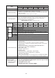
Model name
No. of input
Rated input
voltage
Input voltage
range
Rated input
current
Input
impedance
Surge current
Input ON level
Input OFF level
Response time
(module alone)
Internal current
consumption
(5 VDC)
Operation
indication
External wire
connection
system
Dielectrical
strength
Insulation
resistance
Insulation
system
Common
system
Weight
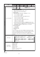
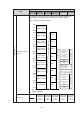
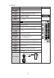
Circuit diagram
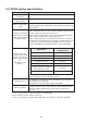
AC input module : JW-211NA
16 points
100/120 VAC (50/60 Hz)
85 to 132 VAC
(50/60 Hz, waveform distortion : 5% or less)
10 mA TYP. (100 VAC, 60 Hz)
8.4 mA TYP. (100 VAC, 50 Hz)
10 k ohm (TYP., 60 Hz), 12k ohm (TYP, 50 Hz)
Max. 480 mA, 0.2 ms (at 132 VAC peak ON)
80 V/7 mA or less
30 V/3 mA or more
OFF to ON : 30 ms or less (100 VAC)
ON to OFF : 40 ms or less (100 VAC)
60 mA max.
LED lights at ON condition
10 P detachable terminal block
(M3.5 x 7 screws, blue)
1500 VAC for 1 minute
(between input terminal and secondary circuit)
500 VDC, 10 M ohm or more
(between input terminal and secondary circuit)
By photo-coupler
1 common line for 8 points
Approx. 220g
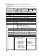
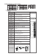
Front view
(2) JW-211NA
JW-211NA
0
1
2
4
5
6
7
0
1
2
4
5
6
7
A
B
COM.B
COM.A
A
B
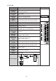
01234567
01234567
COM.A
7
0
COM.B
7
0
Photo-coupler
(A)
(B)
Input
indicator
Internal-circuit
Power
Power