Version 1.1 Produced in May 2002 LCD Control Terminal ZM-42/43/52/72/82 User's Manual (Ladder Monitor Version) Thank you for purchasing our LCD control terminal ZM-42/43/52/72/82 (with a ladder monitor function). This manual describes how to set up the ladder monitor function of the ZM-42/43/ 52/72/82 in order to use it effectively. The other functions of the ZM-42/43/52/72/82 and screen editor software are described in the following manuals. Please read them together with this manual.
Table of Contents Before use Chapter 1: Outline ...................................................................................................... 1-1 Chapter 2: Precautions for use ................................................................................. 2-1 Chapter 3: System Configuration ............................................................................. 3-1 Chapter 4: Connecting to a PC ..........................................................................
Before use [1] Differences from the ZM-70T's ladder monitor function Can use a 32-pixel per character font (smooth 4x character font). However, there is a limitation on the amount of data that can be shown on the screen at one time. Can use custom 16-pixel characters created by the user. The ZM-70T uses a custom 16-pixel character file supplied by SHARP to display ladder chart symbols. The ZM-42/43/52/72/82 series can use this custom 16-pixel character file for characters created by the user.
Chapter 1: Outline The ZM-42/43/52/72/82 series LCD control terminal can display a ladder circuit for a PC (programmable controller) used for facility maintenance. The LCD control terminal does not contain the entire ladder program in itself, just like the ladder software (JW50SP and others). It searches for the ladder program on a network that has the specified coil number, and displays the reconstructed ladder chart.
Chapter 2: Precautions for use (1) Installation location and environment Do not install the LCD control terminal in any of the following locations. - Where flammable gas, solvents, or coolant liquid are present. - In locations with salt or metal dust in the air. - In locations exposed to direct sunlight. (2) Installation precautions Carefully consider operability, maintenance requirements, and environmental hazards when installing an LCD control terminal.
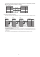
Chapter 3: System Configuration Communication module PG port on a SHARP PC (Connector for a support tool) (When operating) *1 Connection cable (ZM-**) PC model name JW50/70/100 JW50H/70H/100H JW20/20H JW30H Communication module name Control module name PC model name JW50/70/100 JW-50CU/70CU/100CU JW50H/70H/100H JW-50CUH/70CUH/100CUH ZW-20CM JW-20CM JW-20RS JW-20MN JW-22CM JW-21MN JW30H JW-32CUH/H1 JW-33CUH/H1/H2/H3 JW20/20H JW-21CU/22CU Personal computer (When sending an image) ZM-71SE screen ed
Chapter 4: Connecting to a PC [1] Compatible PCs Model setting in the ZM-71SE Sharp: PG port TPB version V1.200 or later PC Module JW50, JW70, JW100 JW50H, JW70H, JW100H Control module ZW-20CM, JW-20CM JW-20MN Satellite net module ME-NET module JW20H, JW30H Control module JW-22CM JW-21MN Satellite net module ME-NET module - Only version 5.8 or later of the JW-20CM can be used for a multi-link connection. Use MODE "4". - Use version V1.200 or later for the TPB file in the ZM-71SE.
Connection to the PG port (support tool connection connector) on a JW-32CUH/H1, JW-33CUH/ H1/H2/H3, JW-21CU/22CU, JW-22CM, or JW-21MN. ZM-** (CN1/TB1) PG port on a JW series PC Signal name No Signal name No +SD 12 +RXD 9 -SD 13 -RXD 10 +RD 24 +TXD 3 -RD 25 -TXD 11 FG 1 FG 1 (2) RS-422 (n:1 multi-link connection) The multi-link connection is only supported on a version 5.8 or later of the JW-20CM.
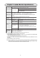
Chapter 5: Ladder Monitor Specifications Call a supplied macro instruction by turning ON a switch. - Touch a switch on the screen.
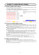
Chapter 6: Ladder Monitor Display 6-1 Outline of ladder monitor display - On a normal display screen, put on an overlap screen. The LCD control terminal displays a ladder monitor on the display area of this overlapped screen. - By entering a coil number using the numeric keys on the screen, a ladder monitor can be displayed on the overlapped screen. (Inputting TMR/CNT number is also available.) Touch a lamp on the error status screen.
6-4 How to set ladder monitor Start up the ZM-71SE software and set according to the setting procedures below. Copy screen data of the basic screen data [LADDER82.Z71] to set a ladder monitor. On the software tool bar, select "File" → "File Manage" → "Screen data file" in that order. Select "LADDER82.Z71" (basic screen data) in the Copy Source column, and enter file name (Ex. "TEST.Z71") in the Copy Target column and click the "OK" button. (See the figure above.) [1] Copy multi overlap No.
[3] Copy macro block (No. 0 to 13) If some macro blocks are already used, change numbers in order not to double the same macro block numbers. Especially, to change description of switch ON macro that is set to contact point search switch of multi overlap No. 0 is difficult, change macro block number already used.
When the symbol/comment is saved in ZM70 format, a "*.mg" file is created by dividing files so each has 256 symbols/comments at maximum. [Ex.] When the number of symbols/comments is 1000 and file name is "TEST.SYC." By saving this file in ZM70 format, four files will be created as "TEST01.MG," "TEST02.MG," "TEST03.MG," and "TEST04.MG." Load the text file (*.MG) having 256 symbols/comments using the software message edit function. - On the basic screen, message block No.
[5] Setting screen for display ladder chart (1) Initial setting in order to use the ladder monitor (Select from edit items). Select "System setting" → "Other settings" → Make possible to use the ladder monitor on the P3 menu. Click the check box " □ Use Ladder Monitor." (See the figure below.) If you cannot put check mark because the characters are changed to meaningless symbols, reset the PLC type to "SHARP: PG port." (2) Set for overlap display of ladder chart on a screen to you want to display.
When "Call" is selected, the "Overlap (Call)" setting dialog opens. Set as shown below. Overlap No.: 0 (Enter No. 0 that was assigned for the call overlap.) Multi Overlap No.: 0 (Enter No. 0 that was assigned for ladder monitor display area.) (3) Set for displaying numeric key display overlap that is used to enter the coil number to search. Click the overlap icon on the parts edit screen. The "Overlap Setting" dialog shown below appears. Then, select "Multi" for "No. 1 Overlap.
When "Multi" is selected, the "Overlap (Multi)" setting dialog opens. Set as shown below. Overlap No.: 1 (Enter No. 1 the same number as assigned for the multi overlap.) Clock the OK button, now the settings for the overlap are complete. On the bar icon at the lower left of the screen, two icons of overlap No. 0 and No. 1 appear. (See the figure below.
(4) Set a switch that is used to display a ladder chart on the screen. Arrange switches on the screen, and set the following in the switch dialog. A B The below describes with an example of setting "05000" switch shown by arrow A. Operation: Press this switch, and the overlap No. 0 is displayed and the LCD control terminal starts to search the OUT05000 coil and displays one network ladder chart having this coil. Setting: Make effective the lamp memory and set the address "0005000.
Click the "Use ON Macro" to enable this function on the "Detail" setting menu. Enter "CALL 0" in the "ON Macro Edit" dialog box. For details of "CALL 0," see page 6-16. Or, with the following "ON Macro Edit" detail, the same operation can be executed. With the settings above, pressing of this switch causes the LCD control terminal to show overlap No. 0 of the ladder display area, searches for OUT05000 coil, and displays a ladder chart of one network having this coil.
(5) Set a switch in order to display numeric keys that are used to enter the coil number on the screen. This paragraph describes an example of setting the switch named "coil number search" shown with arrow B on page 6-8. Operation: Press this switch and the overlap No. 1 is displayed on the screen. Enter any coil/ TMR/CNT number using the numeric keys, and press "Search" on the numeric key display.
(6) Set a switch that is used to search and display a ladder chart linking with the relay mode. Arrange a switch on the screen and set the following on the switch dialog. The below describes setting a switch named "ERR LINK" that is encircled by an ellipse on the figure above. Operation: Press this switch, and if an error message occurs, the LCD control terminal displays overlap No. 0 and searches a coil linking with the relay mode memory, and displays a ladder chart of one network having this coil.
Click "Use ON Macro" to make effective this function on the "Detail" setting menu. For "ON Macro Edit," enter the macro instruction of the figure below. As for macro instruction details, see page 6-24 and after.
[6] System update in order to support the ladder monitor screen data function. In order to display the ladder monitor, the "main program" and "I/F driver" of the LCD control terminal (ZM series) should be updated to support the ladder monitor function. Ladder monitor supported ZM-71SE version: V1.3.0.0 or later - In order to update the system, it may take much time as all the data must be transferred to the main housing.
Ladder monitor supporting version ZM-71SE V1.3.0.0 or later SYSTEM PROG. VER. V1.240 or later * If you make a mistake about version, the "ERROR code 152" is occured. I/F DRV VER V1.200 (For SHARP JW PGPORT) Ladder program VER. 1.200 or later (* Display by pressing the extension program information switch.) * If the extension program information switch is not displayed, the system may not be properly updated. Try updating the system software again.
6-5 Description of ladder monitor screen data 6-5-1 Display area for ladder chart display Specify [Display Area] inside the multi overlap with the following details. The basic screen "LADDER82.Z71" corresponds to multi overlap No. 0. Item Set detail Division No. 0 Foreground White (recommending) Background Blue (recommending) Tile None (recommending) □ Ladder Monitor display Put a check mark in the check box.
[2] How to set macro for ladder circuit display There are four types of parameters to specify searching memory No. for displaying ladder circuit. In addition, two examples can be set. - Parameter type 0 — Switch lamp memory search instruction (1) - Parameter type 1 — Contact point touch search instruction (2) - Parameter type 2 — Scroll, search input (3) - Parameter type 3 — Numeric key memory search instruction (4) - Application example 1 — Any coil No.
Description of multi overlap No. 0 (call overlap) screen For displaying ladder circuit, switches are arranged on a matrix of 15 (horizontal) x 12 (vertical). Secure space for 2 grids (left and right of a switch) and arrange a switch occupying 3 (horizontal) x 2 (vertical) so that the switch is arranged with the same pitch as one of the ladder chart contact points. Note: The screen above is shown with colored switch frames for explanation purpose.
(3) Scroll instruction and search instruction On the basic screen "LADDER82.Z71," these instructions use macro blocks Nos. 2 to 5, and Nos. 7 to 11. These are arranged on the multi overlap No. 0 screen of the "LADDER82.Z71." Select the "Detail" → "ON Macro Edit" → "Call 2 to 5, 7 to 11," in that order to assign these instructions. - SET-LDR: UP-SCROLL Setting display of macro block No. 2 (scroll up: Executes the call with CALL 2) - SET-LDR: DW-SCROLL Setting display of macro block No.
- SET-LDR: FIND+ Setting display of macro block No. 8 (search in positive direction: Executes the call with CALL 8) - SET-LDR: F-RETURN Setting display of macro block No. 9 (search back: Executes the call with CALL 9) - SET-LDR: BF-FIND Setting display of macro block No. 10 (before ladder: Executes the call with CALL 10) - SET-LDR: NX-FIND Setting display of macro block No.
Description of ladder monitor control switches (operate after displaying ladder circuit) Function of ladder control switches that are arranged on the multi overlap screen. 1. "Before LD" switch: Displays the previous circuit of the currently displayed circuit. - This switch is using macro block No. 10 (switch ON macro CALL 10). 2. "Next LD" switch: Displays the next circuit of the currently displayed circuit. - This switch is using macro block No. 11 (switch ON macro CALL 11). 3.
(4) Numeric key memory search instruction - SET-LDR: COIL-FIND Setting display of macro block No. 6 (Numeric key input search: Executes call by CALL 6) On the basic screen "LADDER82.Z71," this instruction is used for macro block No. 6. This is used for ON macro edit of the multi overlap No. 1 "Search" switch. Select the "Detail" → "ON Macro Edit" → "CALL 6," in that order to assign this function.
Numeric key screen setting screen of multi overlap No. 1 Displays data entered using the numeric keys $u1000 Used for macro block No. 6 A switch to select from coil/TMR/CNT. By selecting a switch, the respective lamp lights. Determine the selection by detail of the $u1001. - Description of ON macro edit of the "Search" screen Press the "Search" screen using the "write" switch function; the LCD control terminal writes the coil/TMR/CNT number and executes macro CALL 6.
Display open macro setting of multi overlap No. 1 When the multi overlap is opened, the LCD control terminal turns ON the numeric key memory $u0700 write enable bit (0th line), and makes possible numeric key input. The LCD control terminal first lights the "Coil" lamp and waits for coil number input. (1st to 2nd lines) (5) Any coil No. search instruction If you want to search for any memory coil, but not search for a coil of the switch lamp memory, execute with the following procedures.
(6) Relay mode link search instruction The software can link ladder monitor display by directly searching a coil which is turning ON the error message specified by the cursor, when an error message or the like is displayed with relay mode. For example, on a message of "Limit switch error," you can display the ladder circuit of the coil at which an error occurred by one touch switch operation. - SET-LDR: COIL-FIND Display setting of macro block No.
Setting relay mode memory (set the memory on the dialog below to 10000) If the relay mode memory was changed, set the 9th line of the switch ON macro described in the previous page to the changed memory number. Setting relay mode data output memory (set the relay data output on the dialog below to $u0800) When the data output memory is set to $u0800, a value of which bit of the relay mode memory is selected for $u0802 is entered.
6-6 Description of details displayed on screen when displaying ladder monitor (1) Upper zone of the display area is for displaying ladder program. When a correct ladder circuit is searched, the LCD control terminal displays the ladder circuit and highlights the coil and enters into the circuit monitor operation. (2) At the lower zone of the display area, the LCD control terminal displays information of cursor highlighted position.