
User`s manual


4-1
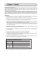
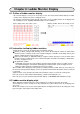
Chapter 4: Connecting to a PC
[1] Compatible PCs
- Only version 5.8 or later of the JW-20CM can be used for a multi-link connection. Use MODE "4".
- Use version V1.200 or later for the TPB file in the ZM-71SE.
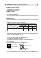
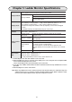
[2] Communication settings
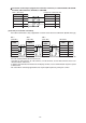
[3] Wiring method
This section describes the cable connection between the LCD control terminal and a PC (control
module, communication module).
Connect a cable to the CN1 connector (TB1 when ZM-52HD is used) on the back of the LCD control
terminal. Connect the other end of the cable to the PG port (connector for a support tool) on a PC.
- When installing a communication module (JW-20CM or the like) in a PC, the PG port on the PC is used
to connect a programmer or ladder software. Therefore, connecting the LCD control terminal to a PG
port on the communication module can be convenient for debugging.
(1) When making an RS-422 connection (a 1:1 connection)
Connection to the PG port (support tool connector) on a JW-50CU/70CU/100CU, JW-50CUH/
70CUH/100CUH, JW-20CM, JW-20RS, or JW-20MN.
Model setting in the
ZM-71SE
PC Module
Sharp: PG port
TPB version
V1.200 or later
JW50, JW70, JW100
JW50H, JW70H, JW100H
Control module
ZW-20CM, JW-20CM
JW-20MN
Satellite net module
ME-NET module
JW20H, JW30H Control module
JW-22CM
JW-21MN
Satellite net module
ME-NET module
- There is no need to make settings on the PC.
However, if the display terminal cannot
complete a connection to a PC, check the
settings on the left using the ZM-71SE software.
metI sliatedgnitteS
deepsrefsnarTspb00291
htgnelataDstib8
ytiraPddO
tibpotSstib2
noitcerrocrorrEmuskcehC
224-SR
4
esu,knil-itlumagnisunehW-
"4"EDOM,metsysenil-2eht
rebmunnoitatS"10"syawlA
Signal name No
+RXD 2
-RXD 15
+TXD 3
-TXD 16
FG 1
Signal name No
+SD 12
-SD 13
+RD 24
-RD 25
FG 1
ZM-** (CN1/TB1)
PG port on a JW series PC