KB-3425LS/K/W KB-4425LS/K/W SERVICE MANUAL S66R264KB442L FREE STANDING/SLIDE-IN RANGE WITH MICROWAVE DRAWER MODELS KB-4425LW pictured KB-3425LS KB-4425LS KB-3425LK KB-4425LK KB-3425LW KB-4425LW WARNING TO SERVICE PERSONNEL: This service manual is intended for use by persons having electrical and mechanical training and a level of knowledge of these subjects generally considered acceptable in the appliance repair trade.
KB-3425LS/K/W KB-4425LS/K/W PRECAUTIONS TO BE OBSERVED BEFORE AND DURING SERVICING TO AVOID POSSIBLE EXPOSURE TO EXCESSIVE MICROWAVE ENERGY (a) Do not operate or allow the oven to be operated with the door open.
KB-3425LS/K/W KB-4425LS/K/W WARNING TO SERVICE PERSONNEL Range units contain circuitry capable of producing very high voltage and current, contact with following parts may result in a severe, possibly fatal, electrical shock. (Example) High Voltage Capacitor, High Voltage Power Transformer, Magnetron, High Voltage Rectifier Assembly, High Voltage Harness, Heating Elements, etc.. Read the Service Manual carefully and follow all instructions. Before Servicing 1.
KB-3425LS/K/W KB-4425LS/K/W SAFE SERVICING PRACTICES To avoid personal injury and/or property damage, it is important that Safe Servicing Practices be observed. The following are some limited examples of safe practices: 1. DO NOT attempt a product repair if you have any doubts as to your ability to complete it in a safe and satisfactory manner. 2. Before servicing or moving an appliance: • Remove the power cord from the electrical outlet, trip the circuit breaker to the OFF position, or remove the fuse.
KB-3425LS/K/W KB-4425LS/K/W MICROWAVE MEASUREMENT PROCEDURE A. Requirements: 1) Microwave leakage limit (Power density limit): The power density of microwave radiation emitted by a microwave oven should not exceed 1mW/cm2 at any point 5cm or more from the external surface of the oven, measured prior to acquisition by a purchaser, and thereafter (through the useful life of the oven), 5 mW/cm2 at any point 5cm or more from the external surface of the oven.
KB-3425LS/K/W KB-4425LS/K/W NOTES
KB-3425LS/K/W KB-4425LS/K/W SERVICE MANUAL FREE STANDING /SLIDE-IN RANGE PRODUCT DESCRIPTION WITH MICROWAVE DRAWER KB-3425LS / KB-3425LK / KB-3425LW KB-4425LS / KB-4425LK / KB-4425LW POWER CONNECTION ANTI-TIP DEVICE FOREWORD This Manual has been prepared to provide Sharp Electronics Corp.
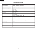
KB-3425LS/K/W KB-4425LS/K/W OVEN SPECIFICATION ITEM DESCRIPTION Power Requirements 120 /208 - 120/240Volts / 46/50 Amperes 60 Hertz Single phase, 3 wire grounded Thermal Oven Heating Elemants Top - 3000W Bottom - 3000W Rear - 2500W Case Dimensions Width 29-7/8" Height 36" Depth 27-7/8 Cooking Cavity Dimensions Width 22-5/8" Height 15-13/16" 3.
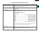
KB-3425LS/K/W KB-4425LS/K/W MICROWAVE DRAWER SPECIFICATION ITEM DESCRIPTION Power Output 1000 watts (IEC TEST PROCEDURE) Operating frequency of 2450MHz Cooking Cavity Dimensions 1.0 Cubic Feet Control Complement Width 17-11/32 Height 5-7/8" Depth 17-1/8" Touch Navigation System Clock ( 1:00 - 12:59 ) Timer (0 - 99 min. 99 seconds) Microwave Power for Variable Cooking Repetition Rate; P-HI................................................... Full power throughout the cooking time P-90............
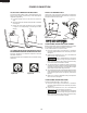
KB-3425LS/K/W KB-4425LS/K/W POWER CONNECTION 208/240 VOLT CONNECTION INSTRUCTIONS ACCESS TO TERMINAL BLOCK The range can be set for 208V or 240V. The voltage setting for your range is pre-set at 240V from the factory. Follow these steps to change the voltage setting. Loosen screw on rear access cover and pull down as illustrated in Figure 6 to access terminal block wiring connection. To close, return to original location and secure screw. 1 Locate the voltage switch on the lower back side of the range.
KB-3425LS/K/W KB-4425LS/K/W 3 Make sure all connections are tightened securely and replace the rear access cover. See Figure 7. connections. Tighten all 3 or 4-wire leads to the terminal block. Follow wire locations shown in Figure 10. IMPORTANT DO NOT LOOSEN the factory installed nut connections which secure the range wiring to the terminal block. Electrical failure or loss of electrical connection may occur if these 3 nuts are loosened or removed.
KB-3425LS/K/W KB-4425LS/K/W 2 DRILL PILOT HOLES AND FASTEN BRACKET ANTI-TIP DEVICE Drill a 1/8-inch pilot hole where screws are to be located. If bracket is to be mounted to the wall, drill pilot hole at an approximate 20 degree downward angle. If bracket is to be mounted to masonry or ceramic floors, drill a 5/32-inch pilot hole 1 3/4-inches deep. The screws provided may be used in wood or concrete material. Use a 5/16 -inch nut-driver or flat head screwdriver to secure the bracket in place.
KB-3425LS/K/W KB-4425LS/K/W KB-3425LS 13
Schematic-Off Condition KB-3425LS/K/W KB-4425LS/K/W N L1 CONTROL S1 S2 YLW 4 4a P1B / 4 YLW RED RED YLW RIGHT FRONT SURFACE ELEMENT INSIDE OUTSIDE WHT P1A / 4A 1a BRN 2a 2 INDICATOR LIGHT PROTECTOR 2a RED RED RED P1 RED WHT L2 / P1 RED YLW RED RED L2 RED BLK L2 N L1 RED L BLK RED WHT BLK WHT 1 3 M5 CONTROL UNIT C3 OVEN SWITCHING POWER SUPPLY UNIT RED 3 1 D1 ORG RED C7 E2 E1 ORG MG THERMAL CUT-OUT BLK RED MICROWAVE DRAWER DOOR OPEN-CLOSE MOTOR RED OVEN
COOK TOP SCHEMATIC (DETAIL) RED RED RED RED RED BLK BLK BLK BLK CONTROL S1 S2 YLW INDICATOR LIGHT YLW YLW YLW RED RED 4 L1 / P2 WHT P1A / 4A RED PROTECTOR RED WHT RIGHT FRONT SURFACE ELEMENT P H1 / 4 WHT P1 / 4 WHT YLW 2 YLW 1a 2a RIGHT REAR PROTECTOR SURFACE ELEMENT YLW CONTROL YLW ORG YLW YLW YLW 4a INSIDE OUTSIDE RED RED P1 2 BRN 2a 1a P1B / 4 BLK P2 L2 RED L2 L1 KB-3425LS/K/W KB-4425LS/K/W H2 / 2 L2 / P1 RED COOK TOP N P1 / 4 WHT 2 WARMER SURFACE ELEMENT
KB-3425LS/K/W KB-4425LS/K/W MICROWAVE DRAWER SCHEMATIC (DETAIL) L2 WHT N BLK L1 BLK RED L L RED WHT SWITCHING POWER SUPPLY UNIT LINE CROSS CAPACITOR 1.0uF 250V NOISE SUPRESSION COIL LINE BYPASS CAPACITOR 0.0033uF 250V RED WHT M1 BLK RED E1 E2 ORG CONTROL UNIT F2 MG THERMAL CUT-OUT BLK RED BLK COM.
KB-3425LS/K/W KB-4425LS/K/W RANGE SCHEMATIC (DETAIL) N BLK RED WHT BLK DOOR SWITCH RED M4 M5 RED M9 YLW M10 BRN M8 ORG M12 RY6 ORG YLW C3 FM CLOSS FLOW FAN MOTOR RY9 BLK RED D1 CM RED OVEN M11 THERMISTOR WHT WHT CONTROL UNIT DOOR LOCK MOTOR SWITCH BLU CONV. MOTOR BRN LM RED WHT WHT RY8 C7 DOOR LOCK MOTOR RY7 WHT WHT ORG OL C5 OVEN LAMP RY10 D3 YLW RY-C E6 E3 WHT GRY ORG BLK CONV.
KB-3425LS/K/W KB-4425LS/K/W TEST PROCEDURES PROCEDURE LETTER A COMPONENT TEST TOUCH CONTROL PANEL ASSEMBLY TEST The touch control panel consists of circuits including semiconductors such as LSI, ICs, etc. Therefore, unlike conventional microwave ovens, proper maintenance cannot be performed with only a voltmeter and ohmmeter.
TEST PROCEDURES PROCEDURE LETTER COMPONENT TEST 4) 5) 6) 7) B KB-3425LS/K/W KB-4425LS/K/W Reconnect all leads removed from components during testing. Re-install the covers. Reconnect the power supply cord after the outer case is installed. Run the oven and check all functions. KEYBOARD UNIT TEST 1. Disconnect the power supply cord, and then disassemble as per "OVEN/MICROWAVE DRAWER DISASSEMBLY" page 40. 2. Open the drawer and block it open. 3. Discharge high voltage capacitor. 4.
KB-3425LS/K/W KB-4425LS/K/W TEST PROCEDURES PROCEDURE LETTER COMPONENT TEST 8. Reconnect all leads removed from components during testing. 9. Re-install the covers. 10. Reconnect the power supply cord after the cabinets are installed. 11. Run the drawer and check all function. D DEFROST TEST WARNING : The unit should be fully assembled before following procedure. (1) Place one cup of water in the center of the turntable tray in the oven cavity.
KB-3425LS/K/W KB-4425LS/K/W TEST PROCEDURES PROCEDURE LETTER COMPONENT TEST STEPS 1 OCCURRENCE CAUSE OR CORRECTION The rated AC voltage is not present between Check supply voltage and oven power cord. Pin Nos. 1and 3 of the 2-pin connecter (CN-B). 2 The rated AC voltage is present at primary side of touch control transformer. Touch control transformer or secondary circuit defective. Check and replace touch control transformer or power unit .
KB-3425LS/K/W KB-4425LS/K/W TEST PROCEDURES PROCEDURE LETTER COMPONENT TEST < Install the new AH sensor. Reconnect all leads removed from components during testing. Re-install the outer case (cabinet). Reconnect the power supply cord after the cabinets are installed. Reconnect the oven to the power supply and check the sensor cook operation as follows: 9-1. Fill approximately 200 milliliters (7.2 oz) of tap water in a 1000 milliliter measuring cup. 9-2.
KB-3425LS/K/W KB-4425LS/K/W TEST PROCEDURES PROCEDURE LETTER G COMPONENT TEST SURFACE ELEMENT CONTROL SYSTEMS Di al Posit ion Contacts Two types of surface elements control systems are covered in this manual. 1. Standard infinite switch. 2. Dual infinite switch. OFF LO-MED HI P2 - P O X X P2 - 4 O X X P1 - 2 O X- C X O - open X - closed P1 Standard infinite switch: The surface elements and standard infinite switches provide an infinite choice of heat settings for cooking.
KB-3425LS/K/W KB-4425LS/K/W TEST PROCEDURES PROCEDURE LETTER COMPONENT TEST between the switch and the element are open. If the meter reads line to line voltage the element is defective. Element does not cycle: If the element does not cycle when the switch is set in a position other than high the switch is defective.
KB-3425LS/K/W KB-4425LS/K/W TEST PROCEDURES PROCEDURE LETTER Both elements do not heat: COMPONENT TEST 2. With the switch turned clockwise to the high position measure the voltage drop between terminals 4 and 2. If the meter reads zero the switch is defective. If the meter reads line to line voltage, go to step 3. Raise the top and locate the two terminals on the element where the wires from terminals 4 and 2 are connected. Measure the voltage drop between these two terminals.
KB-3425LS/K/W KB-4425LS/K/W TEST PROCEDURES PROCEDURE LETTER COMPONENT TEST Refer to the disassembly instructions found on Page 16. H MAGNETRON ASSEMBLY TEST 1. Disconnect the power supply cord. 2. Open the drawer and keep it open. 3. To discharge high voltage capacitor, wait for 60 seconds. 4. To test for an open filament, isolate the magnetron from the high voltage circuit. A continuity check across the magnetron filament leads should indicate less than 1 ohm. 5.
KB-3425LS/K/W KB-4425LS/K/W TEST PROCEDURES PROCEDURE COMPONENT TEST LETTER J SECONDARY INTERLOCK SWITCH TEST 1. 2. 3. 4. Disconnect the power supply cord. Open the drawer and keep it open. To discharge high voltage capacitor, wait for 60 seconds. Isolate the switch and connect the ohmmeter to the common (COM.) and normally open (NO) terminal of the switch. The meter should indicate an open circuit with the drawer open and a closed circuit with the drawer closed.
KB-3425LS/K/W KB-4425LS/K/W PROCEDURE LETTER M TEST PROCEDURES COMPONENT TEST BLOWN MONITOR FUSE TEST 1. Disconnect the power supply cord. 2. Open the drawer and block it open. 3. To discharge high voltage capacitor, wait for 60 seconds. 4. If the monitor fuse is blown when the drawer is opened, check the primary interlock switch, secondary interlock switch and monitor switch according to the "TEST PROCEDURE" for those switches before replacing the blown monitor fuse.
TOUCH CONTROL PANEL ASSEMBLY KB-3425LS/K/W KB-4425LS/K/W OUTLINE OF TOUCH CONTROL PANEL The touch control section consists of the following units. 12) Relay Circuit A circuit to drive the magnetron, fan motor, stirrer motor, convection motor, door lock motor, bottom heater, top heater, convection heater and light the oven lamp. 13) Buzzer Circuit The buzzer is responsive to signals from the LSI to emit audible sounds (key touch sound and completion sound).
KB-3425LS/K/W KB-4425LS/K/W DESCRIPTION OF LSI (IC-1) The I/O signal of the LSIis detailed in the following table. Pin No. Signal I/O Description Signal coming from Transparent electrode (touch key on the LCD). When the 1 key of the transparent electrode is touched, a corresponding signal out of OUT1 of IC-2 will be input into P96 of IC-1. 2 P95 IN Signal coming from Transparent electrode (touch key on the LCD).
KB-3425LS/K/W KB-4425LS/K/W Pin No. Signal I/O 20 INT0 IN Description Signal to synchronize LSI with commercial power source frequency. This is the basic timing for all real time processing of LSI. H : +5V L : GND 6.7 msec. 21 P81 OUT 22 TA4OUT OUT Signal to change the rotational direction is output to the Microwave drawer door open-close motor. 0. sec Signal to sound buzzer. A: Key touch sound. A B: Completion sound. 2.
KB-3425LS/K/W KB-4425LS/K/W Pin No. Signal I/O 47 P47 OUT 48 CS2 OUT 49 P45 OUT 50 P44 OUT 51 P43 OUT 52 P42 OUT 53 P41 OUT 54 P40 IN 55 P37 OUT 56 P36 OUT 57 P35 OUT 58 P34 OUT 59 - 61 A11 - A9 OUT 62 VCC2 IN 63 A8 OUT 64 VSS IN 65 - 70 A7 - A2 OUT 71 A1 OUT 72 A0 OUT 73 P17 OUT 74 P16 OUT 75 P15 OUT 76 P14 OUT Description Reset signal is outout to the LCD.
KB-3425LS/K/W KB-4425LS/K/W Pin No. Signal I/O 77 P13 OUT 78 P12 OUT 79 P11 OUT 80 P10 OUT 81 - 88 D7 - D0 OUT 89 AN7 OUT 90 AN6 IN 91 AN5 IN 92 AN4 IN 93 AN3 IN 94 AN2 IN 95 AN1 IN 96 AVSS IN 97 AN0 IN 98 VREF IN 99 AVCC IN 100 P97 OUT Description “L” level: During fan motor OFF. ON Fan motor (Drawer) driving signal. H: +5V To turn on and off relay(RY5).
KB-3425LS/K/W KB-4425LS/K/W HUMIDITY SENSOR CIRCUIT (1) Structure of Humidity Sensor The humidity sensor includes two thermistors as shown in the illustration. One thermistor is housed in the closed vessel filled with dry air while another in the open vessel. Each sensor is provided with the protective cover made of metal mesh to be protected from the external airflow.
KB-3425LS/K/W KB-4425LS/K/W IC-7 IC-8 OVEN TEMPERATURE/SELF CLEANING CONTROL CIRCUIT 35
KB-3425LS/K/W KB-4425LS/K/W OVEN DOOR LOCK MOTOR CONTROL CIRCUIT 36
KB-3425LS/K/W KB-4425LS/K/W OVEN DOOR LOCK MOTOR DETECTION CIRCUIT 37
KB-3425LS/K/W KB-4425LS/K/W TOUCH CONTROL PANEL SERVICING touch control panel and the oven itself is so short that the two can’t be separated. For those models, check and repair all the controls (sensor-related ones included) of the touch control panel while keeping it connected to the oven. B. On some models, the power supply cord between the touch control panel and the oven proper is long enough that they may be separated from each other.
KB-3425LS/K/W KB-4425LS/K/W PRECAUTIONS FOR USING LEAD-FREE SOLDER 1. Employing lead-free solder The "Main PWB" of this model employs lead-free solder. This is indicated by the "LF" symbol printed on the PWB and in the service manual. The suffix letter indicates the alloy type of the solder. Example: Indicates lead-free solder of tin, silver and copper. 2. Using lead-free wire solder When repairing a PWB with the "LF" symbol, only lead-free solder should be used.
KB-3425LS/K/W KB-4425LS/K/W OVEN / MICROWAVE DRAWER DISASSEMBLY WARNING: Follow all safety precautions beginning on Page 2 before proceeding! Fig. 1 1. Before removing Control Panel, take measures to protect the Cook Top surface and keep Microwave Drawer open to prevent scratches. Control Knobs Retainers 2. Remove all Control Knobs (Fig 1). Glass Key Deco 3. Unscrew all Retainers (Fig 1). GND Deco Screw 4. Unscrew Glass Key Deco screw (1) (Fig 1). 5.
w KB-3425LS/K/W KB-4425LS/K/W Fig. 4 10. Remove screws from Control Panel Frame (Fig 4). Control Panel Frame 11. (KB3425L) - Slide Cook Top forward to unlock from shoulder screws, then remove or reposition (Fig. 5). Fig. 5 (KB4425L) - Before you can Slide the Cook Top forward to unlock it from shoulder screws, you must remove one screw from each right and left slide angle (Fig. 5A). This is done by removing the (3) screws holding the back panel to the side panels (Fig.
KB-3425LS/K/W KB-4425LS/K/W 14. Remove screws from Microwave top Air Duct and take off (Fig. 7). 15. Remove all screws from Microwave Back Plate (Fig. 7). Air Duct Fig. 7 16. Lift Back Plate and remove carefully not to damage any wires (Fig. 7). NOTE: The Microwave Back Plate cannot be completely removed due to wiring. If you need to remove, you will have to unhook all wiring routed through it.
KB-3425LS/K/W KB-4425LS/K/W STOP SWITCH, SECONDARY INTERLOCK SWITCH AND MONITOR SWITCH REMOVAL 2. the drawer and keep it open. 1. Open Disconnect the power supply cord. 3. To discharge the high voltage capacitor, wait for 60 seconds. 4. Remove the Cook Top. 5. Remove the Cook Top Stay (right or left). 6. Remove the screw holding the latch hook to the oven flange. 7. Remove the latch hook from the oven flange. 8. Disconnect the wire leads of each switch. 9.
KB-3425LS/K/W KB-4425LS/K/W DRAWER/SLIDE RAIL REMOVAL AND CHOKE REMOVAL 1.DRAWER DisconnectASSEMBLY the power supply cord. 2. Open the drawer and keep it open. 3. To discharge the high voltage capacitor, wait for 60 seconds. 4. Remove the both right and left Cook Top Stays. 5. Remove (2) Drawer Support Covers from Choke Cover as shown in (Fig. D-1). 6. Insert a putty knife (thickness of about 0.5mm) into the gap between the choke cover and the door frame. 7.
KB-3425LS/K/W KB-4425LS/K/W SWITCH ANGLE REMOVAL/ADJUSTMENT SWITCH ANGLE REMOVAL Fig. S-1 (Locate either the right or left switch angle) 1. 2. 3. 4. Follow the Microwave Drawer disassembly as previously stated. Open the drawer and keep it open. To discharge the high voltage capacitor, wait for 60 seconds. To remove switch, remove screw (1) holding switch to switch angle (Fig. S1). 5. To replace switch angle, remove bottom cover and remove the 2 screws holding the switch lever (Fig. S-2). 6.
KB-3425LS/K/W KB-4425LS/K/W AUTO DRAWER GEAR REMOVAL 1. 2. 3. 4. 5. 5. 6. 7. Follow the Microwave Drawer disassembly as previously stated. Open the drawer and keep it open. To discharge the high voltage capacitor, wait for 60 seconds. Unhook wiring Auto Drawer Gear. Remove the (4) screws holding the auto drawer gear to the bottom cavity angle (Fig. G-1). Pull drawer gear from cavity angle. The drawer gear is now free.
KB-3425LS/K/W KB-4425LS/K/W OVEN DOOR REMOVAL OVEN DOOR ASSEMBLY REMOVAL 1. Disconnect the power supply cord. 2. Open the door to the fully opened position (Fig. O-1). 3. Pull the lock located on both hinge supports up and engage in the hook of the hinge levers. You may have to apply a little downward pressure on the door to pull the locks fully over the hooks (Fig. O-2). 4. Grab the door by the sides, pull the bottom of the door up and toward you to disengage the hinge supports.
KB-3425LS/K/W KB-4425LS/K/W OVEN BAKE ELEMENT REMOVAL 1. 2. 3. 4. 5. 6. Disconnect the power supply cord. Refer to the disassembly instructions as previously stated. Disconnect the wires by removing (2) nuts from element (Fig. O-5) Remove the (2) screws holding the element from inside the oven (Fig. O-6). Pull the Element into the oven. Proceed in reverse to reinstall the Bake Element. Fig. O-5 Fig. O-6 OVEN BROIL ELEMENT REMOVAL 1. 2. 3. 4. 5. 6. Disconnect the power supply cord.
KB-3425LS/K/W KB-4425LS/K/W BLOWER MOTOR REMOVAL 1. 2. 3. 4. 5. 6. 7. Disconnect the power supply cord. Refer to the disassembly instructions as previously stated. Unhook all wiring from Blower Motor (Fig. O-11) Remove tape from Thermistor rear hole. Remove the (2) screws holding the Blower Motor to the Rear Plate. The Blower Motor is now free. Proceed in reverse to reinstall the Blower Motor. Fig. O-11 LOCK MOTOR REMOVAL 1. 2. 3. 4. 5. 6. 7. Disconnect the power supply cord.
KB-3425LS/K/W KB-4425LS/K/W CONVECTION MOTOR/IMPELLER BLADE REMOVAL 1. 2. 3. 4. 5. 6. 7. 8. 9. Disconnect the power supply cord. Refer to the disassembly instructions as previously stated. Unhook all wiring from convection Motor (Fig. C-16). Remove the (8) screws holding the convection cover on from inside the oven (Fig. C-13). Remove the (2) screws holding the convection heater in place (if necessary) (Fig. C-14). Unscrew the convection fan nut by turning it clockwise (Fig. C-14).
KB-3425LS/K/W KB-4425LS/K/W COOK TOP RADIANT HEATERS/HOT SURFACE INDICATOR REMOVAL 1. Disconnect the power supply cord. 2. Refer to the disassembly instructions as previously stated. 3. After Cook Top Assembly is free, turn upside down (glass side down) on a protective surface to prevent scratching (Fig. O-13). 4. Remove the (10) screws from Bottom Plate and place to the side. 5. Remove Heater Protect Cover (Fig. O-14). 6. Remove necessary spring strap from Radiant Element. 7.
WHT BLK WHT H1(RR) H1(LF) H1(LR) WHT w/BRN STRIPE or BRN H2(LF) WHT WHT 4a(RF) WHT w/YLW STRIPE or YLW RED 4 (RF) H2(RR) WHT L2 WHT w/BRN STRIPE or BRN BLK L1 2 (RF) H2(LR) VLR-12V 1 2 3 4 5 6 7 8 9 10 11 12 (TO COOKTOP HARNESS) L1 (RR) ORG L2 (RR) RED L1 (LR) H1 (RR) BLK P (RR) RED P BLK P2 (RF) PILOT LIGHT LEFT YLW GRN YLW S2 (RF) S1 (RF) INFINITE SWITCHES (LEFT SIDE) P (LR) H2 YLW RED RED (LR) L2 H1 WHT w/BRN STRIPE or BRN P (LR) WHT YLW orWHT w/
BLK WHT RED WHT WHT BLK WHT BRN YLW WHT BRN WHT YLW TO DRAWER HARNESS (JST ELP-02V) L1 L2 4 (RF) 4a(RF) H1(RR) H1(LF) H1(LR) H2(RF) H2(RR) H2(LF) H2(LR) TO INFINITE SW HARNESS (JST VLP-12V) 1 2 1 2 3 4 5 6 7 8 9 10 11 12 BLU RF WHT L2 LF YLW LR BLK SURFACE LAMPS RR BRN 2b BLU BRN 2a P1 BLK YLW YLW RED P1B 1 ZONE LEFT FRONT (LF) SMALL 1b YLW YLW YLW BLU 1b 2a WHT BLU BLK 2b 2 ZONE RIGHT FRONT (RF) LARGE WHT P1A 2b BLK BLU BLK BLU 2b P1 WHT YLW YLW BRN 1b 1 ZONE LEFT REAR (LR)
1 2 (COM.)(N.O.) WHT GRN STOP SW EX 1 2 3 4 5 TO CPU CNN (JST XAP-05V-1) RED 1 ORG 2 BLU 3 YLW 4 5 BLK WHT YLW WHT GRN GRY BRN 1 2 3 4 DC MOTOR (JST XMR-05V) EX EX (COM.) (N.O.) BRN GRY DOOR POSITION SWITCH WHT RED ORG EX EX BRN RED BRN BLK (COM.) (N.O.) SECONDARY INTERLOCK SWITCH EX EX WHT EX RED RED RED (N.O.) (COM.) RY-2 EX RED 1 2 3 EX ORG RED ORG (N.O.) (COM.
1 2 3 4 5 6 7 8 9 10 11 12 13 14 15 TO PWB CNH (JST XAP-15V-1) EX BLK (COM) EX BLK (N.O.
(RIGHT) (L2) (LEFT) (L1) TERMINAL RED BLK UL TAPE NO.07 NO.
BLK BLK (LEFT) (L1) 57 TERMINAL WHT RED WHT RED (CENTER) (RIGHT) (N) (L2) ORG EX OVEN LAMP WHT WHT EX 2 LOCK MOTOR BRN BRN (COM) 1 WHT WHT 3 (N.O.) RED VOLTAGE SWITCH (N.C.) BLK YLW (COM) BLK BLK RED (N.O.) TOP HEATER RED BRN (N.C.
KB-3425LS/K/W KB-4425LS/K/W 2 1 4 3 6 5 Transformer CN-A RTRNPA006WRZZ D1 -- D4 1N4002L x4 A-1 CN-H A A 2200uF/35V + C2 C1 A-2 0.1uF/50V H-1 H-2 A-6 VRS1 H-3 A-4 B B 10G471K ZD1 RY2 POWER TRANSFORMER HZ20-1 Q1 KTC1027 D5 DU18D1-1P(M)-R-S RY1 (DRAWER COM.) R2 D7 RY3 (OVEN COM.) DU18D1-1P(M)-R RY4 D8 TOP H.
KB-3425LS/K/W KB-4425LS/K/W 2 1 4 3 5 6 A B B 10KF A C Figure S-3.
KB-3425LS/K/W KB-4425LS/K/W 1 2 4 3 5 6 B B 1 C 6 CNJ CNE ZZRD448AFBWPQ 7 1 D16 D17 D15 A S047081 A 1 D14 RY10 C2 6 D18 5 1 D2 D1 D3 C1 VRS1 R1 D CNH D7 RY3 R3 DIP FUSE 2.5A 15 RY9 ZD1 D13 D4 RY11 CNA CND FA844 D C 2 E CNB 3 1 D8 D10 1 R4 R2 C E CNC D11 E 1 Q1 D12 7 B RY7 RY8 D9 D5 RY6 RY5 RY4 F RY1 F 3 RY2 D6 G G H H Figure S-4.
Q7 C23 R40 C5 C8 Q4 C14 D40 I C O D41 R52 R41 R50 R42 C6 R7 ZD2 R96 R95 D97 R97 D21 D22 R123 C106 R124 R126 C107 R125 C111 R130 R129 I C O C4 D40 C41 D96 Q95 R98 R18 R99 Q97 R16 R16 R17 R131 6 C7 C17 C40 R43 R44 C42 Q21 D20 R58 R57 C52 R54 R53 R64 R66 R67 R65 R62 R63 R61 R60 C43 R51 R45 R46 R47 R48 R49 R56 R55 G8W1 R117 R118 Figure S-5.
KB-3425LS/K/W KB-4425LS/K/W 2 1 4 3 5 6 A A B B (Control lock) 1 C 2 3 Stop Clear (On/Off) 4 5 6 7 8 9 Stop Clear Cook top Warm 0 Setup (On) Oven Light Kitchen Timer D START UPPER MICROWAVE Minute Pluse OVEN OPEN C CLOSE Lower Oven START D (Set Off) R97 R86 R85 R84 R83 R82 R81 R80 E E R89 R71 C74 C70 IC44 44 C70 C80 34 C81 33 C71 C73 CF4 1 23 C76 R74 22 C77 C75 C72 C78 11 12 R76 R72 C75 R73 R77 R90 R93 R91 R92 R78 R79 6 2 F F 1 CNG QPWBFA850DRZZ
KB-3425LS/K/W KB-4425LS/K/W CONTROL PANEL PARTS LIST Note: The parts marked “∆” may cause undue microwave exposure. The parts marked “*” are used in voltage more than 250V. REF. NO. 1- 1 1- 2 1- 3 1- 4 1- 5 1- 6 1- 7 1- 8 1- 9 1-10 1-11 1-12 1-13 1-13 1-14 1-15 1-15 1-16 1-16 1-16 1-17 1-17 1-18 1-18 1-18 1-19 1-19 1-19 1-19 PART NO.
KB-3425LS/K/W KB-4425LS/K/W 2 1 4 3 6 5 CONTROL PANEL 1-18 A 1-17 A 1-14 1-8 1-18 1-16 1-12 B B 1-17 1-1 1-8 1-10 1-14 C C 1-15 1-12 1-11 1-12 D D 1-5 1-12 1-7 1-11 1-7 E E 1-14 1-3 1-13 1-7 1-2 F F 1-6 1-19 G 1-4 CONTROL PANEL HARNESS G 1-13 1-9 H H Actual wire harness may be different from illustration.
KB-3425LS/K/W KB-4425LS/K/W COOK TOP PARTS LIST Note: The parts marked “∆” may cause undue microwave exposure. The parts marked “*” are used in voltage more than 250V. REF. NO. 2- 1 2- 2 2- 3 2- 4 2- 5 2- 6 2- 6 2- 6 2- 6 2- 7 2- 8 2- 9 2-10 2-11 2-12 2-13 2-14 2-14 2-14 2-15 2-16 2-17 2-18 2-19 2-20 2-20 2-21 2-21 PART NO.
KB-3425LS/K/W KB-4425LS/K/W 2 1 4 3 6 5 2-21 A A KB3425L KB4425L 2-6 2-12 2-19 B B 2-6 Rear view 2-12 Rear view 2-20 C C 2-19 2-14 2-2 2-12 2-4 D Front view D 2-17 2-5 2-9 2-3 2-11 2-12 E E 2-10 2-15 2-4 2-16 2-9 F F 2-7 COMMON PARTS 2-18 G G 2-13 2-1 2-12 H 2-8 2-13 Actual wire harness may be different from illustration.
KB-3425LS/K/W KB-4425LS/K/W MICROWAVE DRAWER PARTS LIST Note: The parts marked “∆” may cause undue microwave exposure. The parts marked “*” are used in voltage more than 250V. REF. NO. ∆ * 3- 1 3- 2 3- 3 3- 4 3- 5 3- 6 3- 7 3- 8 3- 9 3-10 3-11 3-12 3-13 3-14 3-15 3-16 3-17 3-18 3-19 3-20 3-21 3-22 3-23 3-24 3-25 3-26 3-27 3-28 3-29 3-30 3-31 3-32 3-33 3-33 3-33 3-34 3-35 3-36 3-37 3-38 3-39 3-40 3-41 3-42 3-43 3-44 3-45 3-46 3-47 3-48 3-49 3-50 3-51 3-52 3-53 3-54 3-55 3-56 3-57 PART NO.
KB-3425LS/K/W KB-4425LS/K/W REF. NO. PART NO.
KB-3425LS/K/W KB-4425LS/K/W 2 1 4 3 MICROWAVE DRAWER 6 5 MICROWAVE DRAWER HARNESSES A A 3-74 3-47 3-55 3-75 3-14 3-28 Actual wire harness may be different from illustration.
KB-3425LS/K/W KB-4425LS/K/W OVEN PARTS LIST Note: The parts marked “∆” may cause undue microwave exposure. The parts marked “*” are used in voltage more than 250V. REF. NO. 4- 1 4- 2 4- 3 4- 4 4- 5 4- 6 4- 7 4- 8 4- 9 4-10 4-11 4-12 4-13 4-14 4-15 4-16 4-17 4-18 4-19 4-20 4-21 4-22 4-23 4-24 4-25 4-26 4-27 4-28 4-29 4-30 4-31 4-32 4-33 4-34 4-35 4-36 4-37 4-38 4-39 4-40 4-41 4-42 4-43 4-44 4-45 4-46 4-47 4-47 4-48 4-48 4-49 4-50 4-51 4-52 4-53 4-54 4-55 4-56 4-57 4-58 4-59 4-60 4-61 PART NO.
KB-3425LS/K/W KB-4425LS/K/W 2 1 4 3 6 5 OVEN UNIT OVEN UNIT HARNESSES A A 4-42 4-40 Actual wire harness may be different from illustration.
KB-3425LS/K/W KB-4425LS/K/W OVEN DOOR PARTS LIST Note: The parts marked “∆” may cause undue microwave exposure. The parts marked “*” are used in voltage more than 250V. REF. NO. 555555555- 1 1 1 2 3 3 3 4 5 PART NO.
KB-3425LS/K/W KB-4425LS/K/W 1 2 4 3 6 5 OVEN DOOR A A 5-2 B B C C 5-1 D D E E 5-5 F F 5-4 G G 5-3 5-4 H H 1 2 4 3 73 5 6
KB-3425LS/K/W KB-4425LS/K/W PACKING PARTS LIST Note: The parts marked “∆” may cause undue microwave exposure. The parts marked “*” are used in voltage more than 250V. REF. NO. 6666666666- 1 2 3 4 5 5 6 7 8 9 PART NO.
KB-3425LS/K/W KB-4425LS/K/W PACKING PACKING CASE KB-3425L Shown SUPPORT CORNERS 6-2 BOILER INSERT 6-3 BOILER PAN 6-8 ANTI-TIP TEMPLATE 6-4 OPERATION MANUAL 6-5 INSTALLION MANUAL 6-7 ANTI-TIP KIT 6-6 6-1 Non-replaceable items 6-9 EXTENDED RACK ASSY x 2 OVEN RACK BOILER PAN RACK 75
KB-3425LS/K/W KB-4425LS/K/W COPYRIGHT © 2006 BY SHARP CORPORATION ALL RIGHTS RESERVED. No part of this publication may be reproduced, stored in retrieval systems, or transmitted in any form or by any means, electronic, mechanical, photocopying, recording, or otherwise, without prior written permission of the publisher. 2006 SHARP CORP. (5R2.00E) Printed in U.S.