3[}" Freestanding Range iNSTALLATiON ANDSERVICEMUSTBEPERFORMED BYA QUALiFiEDiNSTALLER. iMPORTANT:SAVETHiS iNSTALLATiONMANUAL FOR LOCALELECTRICAL iNSPECTOR'S USE. READANDSAYETHESEJNSTROCTJON$ FORFOTOREREFERENCE. iil! HHHHH_ For SAFETY CONSIDERATIONS do not install a range in any combustihle cahinetry accord with the stated clearances and dimensions on page 2.
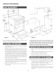
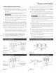
mNSTALLATmON (((( MANUAL .................................................................................................. ......... 29 7/8'_ djustable backsplash width eh I / 18" .... ] 42-48" with adjustaNe backsplash 6 l/e,, [ i 36 '_ countertop height [ [ Maximum depth of cord, 7 3/8" i electrical outlet area Preferred interference with lower oven Figure .-- / 4" \\ \'-\ "_ J _.
iNSTALLATiON t Remo_e the floor covering can withstand heat at !east 9O°F (32.2°C) above room temperature without shrinking, warping or disco!oring. Do not install the range over carpeting unless you place an insulating pad or sheet of 1/4-inch (0.64cm) thick plywood between the range and carpeting. all packing materials from inside the Micrmvave Drawer Never leave chi!dren and the o_en ca_ ity.
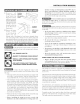
iNSTALLATiON (((( MANUAL .................................................................................................. Risk incorrect or strain of fire or electrical ......... shock exists size range cord kit is used or the Installation relief clamp are disregarded, if an Manua! Do not loosen the nuts which secure the factoryinstalled range wiring to the terminal block while connecting range, Electrica! Nilure or toss of" electrical connection may 4-wire wall receptacle Occur.
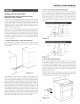
mNSTALLATmON 3oWINg CONNNCTION For existing installations INSTNUCTmONS Befbre wiring the range, re_ ie_ the suggested power source location drawings in Figure 2. If connecting to a 4-wire electrical system: ONLY, refer to Figure 9. t Follow the power supply kit manufacturer's Installation Instructions supplied with the strain relief clamp and install. See Figure 7. 2 Insert the end connectors fbr line 1, line 2 and neutral and tighten securely to the terminal block. See Figure 7.
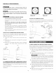
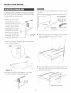
mNSTALLATmON (((( MANUAL .................................................................................................. ......... This backsplash must be installed be%re the range is moved into place. The range backsplash is adjustable so that you can customize it for your particular kitchen situation. The height can be adjusted from the low position (6-inches high) to the highest position (12-inches higN in one inch increments.
iNSTALLATiON MANUAL 2 DNmLLP|LOT HOLES AND FASTEN BNACN:NT Drill a l/s-inch pilot hole where screws are to be located. If bracket is to be mounted to the wall, drill pilot hole at an _pproximate 20 degree downward angle. If bracket is to be mounted to masonry or ceramic floors, drill a 5/32-inch pilot hole 1 3/4 inches deep.
INSTALLATION t tit MANUAL .................................................................................................. ......... The name plate, including model and serial number, is located on the faceplate behind the Micro_ axe Drawer front. Read the BEFORE YOU CALL and operating instruction sections in your Operation Manual. It may saxe you time and expense.