
Installation guide
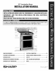


|NSTALLAT[ON MANUAL
NORMAL iNSTALLATiON STEPS
ANTI-TIP BRACKET iNSTALLATiON iNSTRUCTiONS
iMPORTANT SAFETY WARNING
To reduce the risk of tipping of the range, the range must be secured
to the floor by properly installed Anti-Tip bracket and screws packed
with the range. Failure to install the Anti-Tip bracket will allow the
range to tip over if excessive weight is placed on an open door or if
a child climbs upon it. Serious injury might result from spilled hot
liquids or from the range itself.
If range is ever moved to a different location, the Anti-Tip bracket
must also be moved and installed with the range. Instructions are
provided for installation in wood or cement fastened to either the floor
or wall. When installed to the wall, make sure that screws completely
penetrate dry wall and are secured in wood or metal. When fastening
to the floor or wall, be sure that screws do not penetrate electrical
wiring or plumbing.
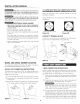
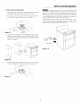
t LOCATE THE BRACKET - USING THE TEMPLATE
The bracket may be located on either the left or right side of the
range. Refer to figure 12b to locate the bracket if template is not
available.
Mark the floor or wall where left or right side of the range will be
located. If rear of range is against the wall or no further than 1
i/4-inches from wall when installed, you may use the wall or floor
mount method. See Figure 13. If molding is installed and does not
allow the bracket to fit flush against the wall, remove molding or
mount bracket to the floor. For wall mount, locate the bracket by
placing the back edge of the template against the rear wall and the
side edge of template on the mark made referencing the side of the
range. Place bracket on top of template and mark location of the
screw holes in wall. If rear of range is further than 1 l/4-inches from
the wall when installed, attach bracket to the floor. See Figure 14. For
floor mount, locate the bracket by placing back edge of the template
where the rear of the range will be located. Mark the location of the
screw holes, shown in template.
2 DRILL PILOT HOLES AND FASTEN BRACKET
Drill a t/s-inch pilot hole where screws are to be located. If bracket
is to be mounted to the wall, drill pilot hole at an approximate 20
degree downward angle. If bracket is to be mounted to masonry or
ceramic floors, drill a 5/32-inch pilot hole 1 3/4 inches deep. The
screws provided may be used in wood or concrete material. Use a
5/16-inch nut-driver or flat head screwdriver to secure the bracket
in place.
_! {_ max11/4''
leveling
wall mount
Figure t 2A
\\_"_ _he_The edge of the template
_/ should be aligned with the left
_/ or right edge of the range.
1
J
13 3/8" from the center of
the wall opening to the edge
of the backet.
floor mount _ l_i
plate
bracket
Figure t 3
[ [_ morethan
leveling leg 11/4"
wall
floor mount
Figure t 4,
bracket
Figure t 2B
6