
Installation guide
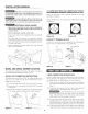


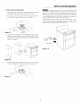

3 LEVEL AND POS|T|ON RANGE
• Measure from the countertop to the floor height to determine
the height that the back of the range needs to be set at.
Loosen legs and lock nuts to set level of the range. (Note that
the lock nuts are only on the rear feet). See Figure 15.
Range Leg
Lock Nut
Figure t S (Rear leg only)
• Adjust the back leveling legs with an adjustable wrench or pliers.
Measure from the floor to the top of the cooktop glass (X) and
adjust the legs to match the measurement (Y) taken from the
cutout. See Figure 16.
J
(Y") (X")
top of of cooklo
countefiop glass
• After leveling, tighten the lock nuts on the rear to prevent the
feet from turning when sliding into position. See Figure 17.
INSTALLATION MANUAL
A minimum clearance of t/s-inch is required between
the bottom of the range and the leveling leg to allow room for the
bracket. Use a level to check your adjustments. Plug range into
properly prepared electrical receptacle or if hard wired, check that
it was completed properly. Check floor condition for evenness and
stability. Slide range back into position. See Figure 18.
Visually check that rear leveling leg is inserted into and fully secured
by the Anti-Tip bracket by looking underneath the range with a
flashlight and carefully attempt to tilt it forward.
,.../
1 5/8" to edge" \
of bracket _ \ \ \
Range Slide _ \\_\\
\ ,
\
Figure t8