
Installation guide


iNSTALLATiON MANUAL
36"
to bottom
of cooktop
surfece
31 1/4"
glass end
control panel
29 7/8"
If using countertop with integrated
drip edge, remove 5/8" to make
flush as illustrated.
5/8" min.
minimum 30"
to bottom of
cabinet over
18"
to upper
cabinets
door width
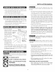
Figure 1 contains many range measurements for reference when
planning your kitchen and/or range location.
Maximum
depth of cord,
plug and
receptacle box
is 4" to prevent
interference
with lower
oven.
Figure 2
\\
\\
\\
preferred electrical _"_
outlet area
30"
opening width
36 _'
countertop
height
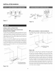
* Provide adequate clearances between the range and adjacent
combustible surfaces.
* Dimensions that are shown in Figure 2 must be used. Given
dimensions provide minimum clearance. There needs to be a
30-inch minimum clearance between the top of the cooking
surface and the bottom of unprotected wood or metal cabinets or
a 24-inch minimum when bottom of wood or metal cabinets are
protected by not less than a 1/4-inch flame retardant millboard
covered with not less than no. 29 msg sheet-steel, 0.015-inch
stainless steel, 0.024-inch aluminum or 0.020-inch copper. Note
that the gray" shaded area on Figure 2 indicates the location for
the electrical receptacle/connection.
* Contact surface must be solid and level Pay" special attention
to the floor. Be sure it is solid enough for the weight of the
range. Check that the floor covering is smooth and flat and that
it adheres to the sub-floor solidly'.
Check location where the range will be installed for proper
electrical supply.
112" minimun ut --
flat area
Figure 3
31 1/4"
30"
cutout
[]
23 1/8" cutout
To eliminate the risk of burns or fire by reaching over the
eooktop, cabinet storage space located above the cooktop should
be avoided. If cabinet storage is to be provided, the risk can be
reduced by installing a range hood that projects horizontally a
minimmn of 5" beyond the bottom of the cabinets.