
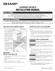
Installation guide
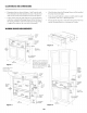

CLEARANCESANDDiMENSiONS
* Dimensions that are shown in Figures 1 and 2 must be used.
Given dimensions provide minimum clearance. The electrical
outlet can be located in the shaded areas shown in Figure 6.
* Contact surface must be solid and level. Pay special attention
to the floor on which the Warming Drawer will sit. The floor of
the opening should be constructed of plywood strong enough
to support the weight of the oven (about 100 pounds).
* Check location where the Warming Drawer will be installed
for proper electrical supply.
* Your oven can be built into a cabinet or wall by itself or under
a gas/electric wall oven, or Warming Drawer.
Be sure that the clearance of the floor between the wall oven
and the Warming Drawer is a minimum of 2-inches.
WARMINGDRAWERMEASUREMENTS
1t/2"xW'
Anti-Tip
block
i9" to bottom
of Anti-Tip
block
ning
36"
countertop ........ Floor must
height support 100 Ibs.
Optional Microwave
Drawer Cutout
illustrated in sketch.
Floormust
st
100 Ibs.
Electricaloutlet
location \
36"
countertop
height
30"
_abinet rain.
Figure 2
24V, "to top of floor
(recommended)
Figures 1, 2 and 4 contain many
Warming Drawer measurements
for reference when planning the
drawer's location. See Figure 5,
84"
page 3, for suggested Warming wall
cabinet
Drawer electrical layout.
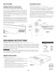
b 6" _ 1W'x%"
Anti-Tip
3V2"
14 _%e"
to bottom
of Anti-Tip
block
1W'x _!
_._Anti-Tip
block
9"
must
opening support
100 Ibs.
7'_/4"to topof floor
([ec0mmended)
pverlap. . mindepth
Allow ¾"
I _._._overlap.
[.....
30"
cabinet mm.
Figure 4
I
i
i
Optional
walloven
cutout
in sketch
(6") _ 1W'x t/_"
block
.....Floor must
support 100 Ibs.
) of floor
(recommended)
1:2