LC-20B8U-S LC-20B9U-S LC-20B9U-SM SERVICE MANUAL S45H7LC20B9US LCD COLOR TELEVISION MODELS LC-20B8U-S LC-20B9U-S LC-20B9U-SM In the interests of user-safety (Required by safety regulations in some countries) the set should be restored to its original condition and only parts identical to those specified should be used. CONTENTS Page » » » » » » » » » » » » » IMPORTANT SERVICE SAFETY PRECAUTION .........................................................................................2 SPECIFICATIONS ..
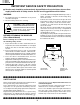
LC-20B8U-S LC-20B9U-S LC-20B9U-SM IMPORTANT SERVICE SAFETY PRECAUTION Ë Service work should be performed only by qualified service technicians who are thoroughly familiar with all safety checks and the servicing guidelines which follow: • Use an AC voltmeter having with 5000 ohm per volt, or higher, sensitivity or measure the AC voltage drop across the resistor.
LC-20B8U-S LC-20B9U-S LC-20B9U-SM PRECAUTIONS A PRENDRE LORS DE LA REPARATION Ë Ne peut effectuer la réparation qu' un technicien spécialisé qui s'est parfaitement accoutumé à toute vérification de sécurité et aux conseils suivants. • Utiliser un voltmètre CA d'une sensibilité d'au moins 5000Ω/V pour mesurer la chute de tension en travers de la résistance.
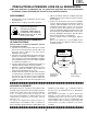
LC-20B8U-S LC-20B9U-S LC-20B9U-SM Precautions for using lead-free solder 1 Employing lead-free solder "All PWBs" of this model employs lead-free solder. The LF symbol indicates lead-free solder, and is attached on the PWBs and service manuals. The alphabetical character following LF shows the type of lead-free solder. Example: LFa Indicates lead-free solder of tin, silver and copper. 2 Using lead-free wire solder When fixing the PWB soldered with the lead-free solder, apply lead-free wire solder.
LC-20B8U-S LC-20B9U-S LC-20B9U-SM SPECIFICATIONS Items LCD panel Number of dots Video color systems TV Standard (CCIR) TV Tuning System TV function STEREO CATV Y/C FILTER Brightness Viewing angles Audio amplifier Speakers INPUT1 INPUT2 INPUT3 Terminals INPUT4/OUTPUT INPUT5 Antenna Headphone OSD language Power supply Power consumption Weight Model LC-20B8U/LC-20B9U 20" Advanced Super View & BLACK TFT LCD 2,359,296 dots XGA N358, N443, PAL, PAL-M, PAL-N, SECAM, PAL-60 NTSC/PAL-M/PAL-N PLL 181 ch.
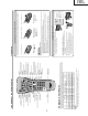
)/( ) INPUT MENU POWER ) POWER/WAKE UP TIMER indicator lights up green when the power is on, and red when in the standby mode (the indicator will not light when the main power is off), and orange when the wakeup timer is set (the indicator will light when in the standby mode). POWER/WAKE UP TIMER indicator The OPC indicator lights up green when "OPC" is set to "ON". OPC (Optical Picture Control) indicator Plug the headphone mini-plug into the headphone jack located on the front of the main unit.
Channel Select Sets the channel. CH ( )/( ) Selects a channel. FLASHBACK Returns to the previous channel. CC Displays Closed Caption subtitles. INPUT Switches the input source between INPUT1, INPUT2, INPUT3, INPUT4, INPUT5 (PC) and TV mode. MENU Displays the menu screen. ' / " / \ / | (Cursor control) Selects a desired item on the screen. BACKLIGHT Adjusts the brightness of the screen. AV MODE Selects preferred AV MODE. DISPLAY Displays the receiving channel and the current time for 10 seconds.
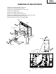
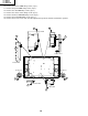
LC-20B8U-S LC-20B9U-S LC-20B9U-SM DIMENSIONS Unit: inch (mm) 13 19/32 (345) 17 31/64 (444) 5 9/32 (134) 2 11/16 (68) 1 25 /8 (638) 3 5/8 (92) 16 17/64 (413) 10 3/32 (256) 12 5/32 (308.4) 9 2 /64 (54) 17 29/64 (443) 15 21/64 (389) 16 11/64 (410.
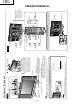
LC-20B8U-S LC-20B9U-S LC-20B9U-SM REMOVING OF MAJOR PARTS 1. Remove the stand cover fixing screw (1 pc.). 2. Remove the stand fixing screws (4 pcs.). 3. Remove the carrying handle fixing screws (4 pcs.). 4. Remove the terminal cover. 5. Remove the terminal screws (4 pcs.). 6. Remove the cabinet B fixing screws (9 pcs.). 7. Remove the cabinet B after opening from the direction of an arrow. 8. Remove the stand angle fixing screws (5 pcs.). 9. Disconnect all the connectors from all the PWBs.
LC-20B8U-S LC-20B9U-S LC-20B9U-SM 10. Remove the inverter PWB fixing screws (3 pcs.). 11. Remove the power PWB fixing screws (6 pcs.). 12. Remove the sub PWB fixing screws (4 pcs.). 13. Remove the chassis frame fixing screws (3 pcs.). 14. Remove the R/C, LED PWB fixing screws (2 pcs.). 15. Remove the main PWB fixing screws (4 pcs.). 16. Remove the 4 lock screws each from the right and left speakers and take out both the speakers.
LC-20B8U-S LC-20B9U-S LC-20B9U-SM » Precautions in handling the LCD panel 1. Handle it in a clean room. (above 50% humidity) 2. The worker must wear an earth band. 3. Be careful not to drop, vibrate and shock the panel. 4. Use an ionizer. (within 30 cm) 17. Remove the three lock screws from the LCD panel, and detach the LCD panel unit. 18. Remove the prism sheet (H), (V), diffusion sheet and diffusion plate. 19. Remove the lamp unit from the lamp holder (top).
LC-20B8U-S LC-20B9U-S LC-20B9U-SM »Precautions in servicing the side-B (backside) of the main PWB unit 1. Disconnect the FFC for connection between the main PWB (SC1201) and LCD panel (CN1), and then connect the service-specific extension FFC (flat cable) (QCNW-C458WJQZ). 2. Disconnect the SC2001 side of the lead from between the main PWB (SC2001) and the sub PWB (P3401), and then connect the service-specific extension cord (QCNW-D402WJQZ). 3.
LC-20B8U-S LC-20B9U-S LC-20B9U-SM ADJUSTING PROCEDURE OF EACH SECTION 1. Preparations before adjustment (1) Keep the AC power cable directly plugged in a wall outlet. AC110V~240V [1] Adjustment procedures 1-1. Adjusting the checker Power on (initialization) → Setting the model number and screen size 1-2.
LC-20B8U-S LC-20B9U-S LC-20B9U-SM [4] Initialization 4-1. Connect both pins (81) and (82) of IC2001 (microprocessor) to GND, and turn on the power. 4-2. Make sure the model number "A628" is selected. *Note: This setting cannot be changed. 4-3. Make sure "20" (inches) is selected for the screen size. *Note: This setting cannot be changed.
LC-20B8U-S LC-20B9U-S LC-20B9U-SM Reference (Onscreen display of adjustment process menu page 2) 0 0 1 2 3 4 5 6 7 8 9 10 11 12 13 14 15 16 17 18 19 20 21 22 23 24 25 26 B I A S 2 1 | C 2 T A M P 3 Y D A T 4 T A M P H 5 N T S C T 6 P A L - 7 P A L - O M L A 4 5 0 1 5 5 1 5 7 1 5 8 8 5 A M P M T A M P 9 1 N T A M P 9 1 8 Y Data (White 75%) 5-4.
LC-20B8U-S LC-20B9U-S LC-20B9U-SM 6-2. Intial value of factory settings Setting ranges MENU PICTURE AV MODE STANDARD/DYNAMIC/DYNAMIC(FIXED)/MOVIE/GAME OPC BACKLIGHT ON/OFF BRIGHT/NORMAL/DARK/VARIABLE 1 (DARK) ~ 9 (NORMAL) ~ 17 (BRIGHT) 0 ~ 60 -30 ~ +30 -30 ~ +30 -30 ~ +30 -10 ~ +10 CONTRAST BRIGHTNESS COLOR TINT SHARPNESS ADVANCED COLOR TEMP.
LC-20B8U-S LC-20B9U-S LC-20B9U-SM LIST OF THE ADJUSTMENT PROCESS MODE MENU For calling the adjustment process mode and keying in this mode, refer back to "ADJUSTING PROCEDURE OF EACH SECTION". DEFAULT CHART OF ADJUSTMENT PROCESS 1ST HIERARCHICAL ITEMS Page No. Item Initial Value Function Response precautions on servicing (Do not change other items than designated.
LC-20B8U-S LC-20B9U-S LC-20B9U-SM Page No. Initial Item Function Value Response precautions on servicing (Do not change other items than designated.) PC AD ADJUSTMENT 8 AUTO GAIN2 AUTO OFFSET2 PCAD R GAIN PCAD G GAIN PCAD B GAIN PCAD R OFFSET PCAD G OFFSET PCAD B OFFSET RGTAR GGTAR BGTAR RGCAL GGCAL BGCAL ROCAL GOCAL BOCAL AD9883 GAIN AUTO ADJUSTMENT OFF/RUN AD9883 OFFSET AUTO ADJUSTMENT OFF/RUN REFER TO METHOD OF ADJUSTMENT. REFER TO METHOD OF ADJUSTMENT. REFER TO METHOD OF ADJUSTMENT.
LC-20B8U-S LC-20B9U-S LC-20B9U-SM Page No. Initial Item Value Function Response precautions on servicing (Do not change other items than designated.
LC-20B8U-S LC-20B9U-S LC-20B9U-SM Page No.
LC-20B8U-S LC-20B9U-S LC-20B9U-SM Page No.
LC-20B8U-S LC-20B9U-S LC-20B9U-SM DEFAULT CHART OF OTHER ADJUSTMENT PROCESS ITEMS Page No. Item Initial Value Function Response precautions on servicing (Do not change other items than designated.) OTHERS OTHERS1 OTHERS OTHERS2 DAC DATA L ERROR WAIT L ERROR H TIME TV AUTO GAIN PWM FREQ PWM DUTY OPC THRESHOLD — 15s 1.
LC-20B8U-S LC-20B9U-S LC-20B9U-SM PUBLIC MODE SETTING PROCEDURE 1. How to start Public Mode » There are the following two ways to get the public mode setup screen displayed. 1 1) Press the "INPUT" and "VOL (+)" keys on the set at once and turn on the power. 2) Get the password input screen displayed. Procedure » The input starts with the leftmost digit. » Use the numeric keys [1] thru [9] and [10/0] keys on the remote controller. The other keys are not acceptable.
LC-20B8U-S LC-20B9U-S LC-20B9U-SM 2. How to exit Public Mode There are the following ways to quit the public mode setup screen. » Turn off "PUBLIC MODE" in the adjustment process mode. (✩) ← This way alone is not for quitting the setup screen, but for quitting the mode itself. » Turn off the power with the "POWER" key. (★) » Select "ENTER". (★) » Move the cursor to "RESET" and press the "FLASHBACK" key. (Back to the normal mode screen)(✩) ★ ... "PUBLIC MODE" stays on in the adjustment process mode. ✩ ...
LC-20B8U-S LC-20B9U-S LC-20B9U-SM 5. On Setting Items * "EZ-SETUP" discussed below indicates "EZ-SETUP after the first power-on". (1) MAXIMUM VOLUME Adjustment from 1 to 60 (no loop) Selection 60 Default Sound volume can not be adjusted higher than the preset value. Explanation Limit in Setting » When the sound volume is set lower than 59, only figures are displayed and the sound volume bar is not displayed. » The maximum sound volume for ON-timer (Wake up timer) is limited also to the preset value.
LC-20B8U-S LC-20B9U-S LC-20B9U-SM (3) VOLUME FIXED LEVEL Selection Default Explanation Limit in Setting Exception Remarks Adjustment from 1 to 60 (no loop) 20 The sound volume to be fixed by "Volume fixed" is determined. None None Setting is valid only when "Volume fixed" is selected for "fixed". This must be confirmed actually by changing also the sound volume in accordance with setting.
LC-20B8U-S LC-20B9U-S LC-20B9U-SM (7) ON SCREEN DISPLAY Selection between "Yes" , "Limited" (loop provide) Yes The following OSD displays are made ineffective. Displays of menu group, channel call, sound volume bar and direct key call Limit in Setting » ON-timer (Wake-up timer) is cleared and set to "OFF". » Set time of the OFF-timer (SLEEP TIMER) is cleared. » Setting of the no-signal power-OFF (AUTO POWER OFF) is cleared to "OFF". » Setting of the no-operation power-OFF is cleared to "OFF".
LC-20B8U-S LC-20B9U-S LC-20B9U-SM (9) INPUT MODE FIXED Selection between "Variable" and "Fixed" (loop provide) – (Variable) The input mode is fixed at the input source or the channel set at the "Input mode start" in 9 and other input sources and channels can be made non-selectable. Limit in Setting » With the execution of hotel mode, the input source is forced to change to that set by "Input mode start" and the channel switching and input switching are prohibited thereafter.
Check IC801 and its peripheral circuits as well as the LCD panel voltage and waveform. Yes 29 Check IC801 and its peripheral circuits. Check the IC801 signal input line. No Check the related lines, IC801 itself and its peripheral circuits.
Check the load of IC701 thru IC703. Yes Is the output voltage of IC7002 and IC7001 as specified? Yes Are the secondary outputs of T7001 +5V, 12V, +35V and +9V? Yes Is there DC 12V input at T7001 and pin (8) of IC7301? Yes Are F7701 as specified? No No No No Check the load of IC7002 and IC7001 and its peripheral circuits. Yes Is pin (10) of IC7002 and IC7001 at "H"? Check the secondary load of T7001.
No PC pictures come out. No pictures come out (2/2). Is the input No Check the IC801 VIDEO at pin (40) line and its of IC801 peripheral as parts. specified? 31 No Check the power supply line. Check Q401, Q402 and Q403. Check the output of IC801, the input and output of IC1201 and their peripheral parts.
Check the speakers and their peripheral parts. Yes Are inputs at pins (2) and (4) as well as outputs at pins (8) and (12), all of IC3304, as specified? Yes Are input and output of IC3201 as specified? Yes Is pin (53) of IC2001 at “L”? Yes Perform the following checking.
No input 3, input 4 colors come out. Check IC801 and its peripheral circuits. Yes Check IC1201, No Does the test its peripheral pattern of the circuitry and the LCD controller LCD panel. come out properly? No TV colors come out. No input 1, input 2 colors come out. No Is the input at pin (5) of IC3401 as specified? Yes 33 Check the output of IC801, the input and output of IC1201 and their peripheral parts.
LC-20B8U-S LC-20B9U-S LC-20B9U-SM MAJOR IC INFORMATION P1_0/D8 P1_1/D8 P1_2/D10 P1_3/D11 P1_4/D12 P1_5/D13/INT3 P1_6/D17/INT4 P1_7/D15/INT5 P2_0/AN2_0A0(/D0/) P2_1/AN2_1A1(/D1/D0) P2_2/AN2_2A2(/D2/D1) P2_3/AN2_3A3(/D3/D2) P2_4/AN2_4A4(/D4/D3) P2_5/AN2_5A5(/D5/D4) P2_6/AN2_6A6(/D6/D5) P2_7/AN2_7A7(/D7/D6) VSS P3_0/A8(/_/D7) VCC2 P3_1/A9 P3_2/A10 P3_3/A11 P3_4/A12 P3_5/A13 P3_6/A14 P3_7/A15 P3_0/A16 P3_1/A17 P3_2/A18 P3_3/A19 1. IC2001 (RH-iXA628WJN1Q), (RH-iXA628WJZZQ) 1-1.
LC-20B8U-S LC-20B9U-S LC-20B9U-SM 1-2. Pin Functions Pin No.
LC-20B8U-S LC-20B9U-S LC-20B9U-SM Pin No.
1 DVDD3.3 2 PXD24 3 PXD25 4 PXD26 5 PXD27 6 VDIN 7 HDIN/FBIN 8 DVDD3.3 9 DGND 10 VRPD 11 VROD 12 VRMD 13 VRND 14 AVDDD2 15 AVSSD2 16 AVDDD1 17 AVSSD1 18 VRPC 19 VROC 20 VRMC 21 VINC 22 AVDDC2 23 AVSSC2 24 AVDDC1 25 AVSSC1 26 DVDD 27 DVSS 28 VRPB 29 VROB 30 VRMB 31 VIM1B 32 AVDDB2 33 VIM2B 34 AVSSB2 35 AVDB1 36 AVSSB1 37 VRPA 38 VROA 39 VRMA 40 VIM1A 41 AVDDA2 42 VIN2A 43 AVSSA2 44 VIN3A 45 AVDDA1 46 AVSSA1 47 SVSS 48 DVDD3.3 49 DGND 50 RESET 51 QOECTL 52 SDA 53 SCL 54 DVDD3.3 55 DGND 56 DVDD1.
LC-20B8U-S LC-20B9U-S LC-20B9U-SM 2-2. Pin Functions Pin No.
LC-20B8U-S LC-20B9U-S LC-20B9U-SM Pin No. Pin name 58 MPWEL 59 MPOE 60 MPCE 61 MPAH/PCXLK1 62 DVDDSD 63 MDQ15/C656IN7 ' 64 MDQ14/C656IN6 ' 65 MDQ13/C656IN5 66 MDQ12/C656IN4 67 MDQ11/C656IN3 ' 68 69 70 71 DVDD3.3 DGND DVDD1.
LC-20B8U-S LC-20B9U-S LC-20B9U-SM Pin No.
LC-20B8U-S LC-20B9U-S LC-20B9U-SM Pin No.
LC-20B8U-S LC-20B9U-S LC-20B9U-SM BLOCK DIAGRAM I2C H TUNER TU3401 I2C SUB UNIT TV-V SIF V2-IN EDID E2PROM IC401 PC-RGB IN SC401 AV SELECT IC3401 PC-R,G,B,H,V 5V 31V INPUT4 /OUTPUT J3403 G L2/R2-IN/OUT PC-AUDIO-IN J3409 PC-L,PC-R INPUT3 J3401 J3403 F AV2 IN/OUT SWITCH IC3404 Q3413 Q3410 Q3414 V2-OUT I2C V2-OUT Y, PB, PR L2, R2-IN REG IC80 A-D CONVERTE IC8701 L, R-OUT Y V1, SY,SC, L1, R1, S-SW 3.
LC-20B8U-S LC-20B9U-S LC-20B9U-SM MA IN UNIT REG. IC805 M 5V I2C 3.3V I2C VIDEO PROCESSER IC801 3.3V A-D CONVERTER IC8701 AD-CKO,HSO,VSO R, G, B RSDS TRANSMITTER IC1201 (VIDEODECODER) (3D Y/C) (I/P) (QS) TV-V,V,SY, SC,Y I2C CK,R,G,B L_R,REV,LS,GSP1,GSP2,POWER,GCK,U_D REG. IC1706 17V 1.8V REG. IC802 3.3V LCD PANEL INV_OFL,INV_OSC 14.6V -6.5V 35V -12V IC1703 32V CVIN I2C INV_POW,L_ERR . 03 5V REG. IC2011 MPU IC2001 3WIRE POW,AC_CTRL(POWERUNIT) 3.3V 5V 17V 3.
LC-20B8U-S LC-20B9U-S LC-20B9U-SM OVERALL WIRING DIAGRAM H G F E D C B A 1 2 3 4 5 6 44 7 8 9 10
LC-20B8U-S LC-20B9U-S LC-20B9U-SM 10 11 12 13 14 15 45 16 17 18 19
LC-20B8U-S LC-20B9U-S LC-20B9U-SM DESCRIPTION OF SCHEMATIC DIAGRAM VOLTAGE MEASUREMENT CONDITION: 1. The voltages at test points are measured on the stable supply voltage of AC 120V. Signals are fed by a color bar signal generator for servicing purpose and the above voltages are measured with a 20k ohm/V tester. INDICATION OF RESISTOR & CAPACITOR: RESISTOR 1. The unit of resistance “Ω” is omitted. (K=kΩ=1000 Ω, M=MΩ). 2. All resistors are ± 5%, unless otherwise noted. (K= ± 10%, F= ± 1%, D= ± 0.5%) 3.
LC-20B8U-S LC-20B9U-S LC-20B9U-SM SCHEMATIC DIAGRAM Ë R/C, LED Unit (LC-20B9U-S) H G F E Ë R/C, LED Unit (LC-20B8U-S, LC-20B9U-SM) D C B A 1 2 3 4 47 5 6
LC-20B8U-S LC-20B9U-S LC-20B9U-SM ËMAIN Unit-1/7 (LC-20B9U-S) H G F E D C B A 1 2 3 4 5 6 48 7 8 9 10
LC-20B8U-S LC-20B9U-S LC-20B9U-SM 10 11 12 13 14 15 49 16 17 18 19
LC-20B8U-S LC-20B9U-S LC-20B9U-SM ËMAIN Unit-1/7 (LC-20B8U-S, LC-20B9U-SM) H G F E D C B A 1 2 3 4 5 6 50 7 8 9 10
LC-20B8U-S LC-20B9U-S LC-20B9U-SM 10 11 12 13 14 15 51 16 17 18 19
LC-20B8U-S LC-20B9U-S LC-20B9U-SM ËMAIN Unit-2/7 (LC-20B9U-S) H G F E D C B A 1 2 3 4 5 6 52 7 8 9 10
LC-20B8U-S LC-20B9U-S LC-20B9U-SM 10 11 12 13 14 15 53 16 17 18 19
LC-20B8U-S LC-20B9U-S LC-20B9U-SM ËMAIN Unit-2/7 (LC-20B8U-S, LC-20B9U-SM) H G F E D C B A 1 2 3 4 5 6 54 7 8 9 10
LC-20B8U-S LC-20B9U-S LC-20B9U-SM 10 11 12 13 14 15 55 16 17 18 19
LC-20B8U-S LC-20B9U-S LC-20B9U-SM ËMAIN Unit-3/7 (LC-20B9U-S) H G F E D C B A 1 2 3 4 5 6 56 7 8 9 10
LC-20B8U-S LC-20B9U-S LC-20B9U-SM 10 11 12 13 14 15 57 16 17 18 19
LC-20B8U-S LC-20B9U-S LC-20B9U-SM ËMAIN Unit-3/7 (LC-20B8U-S, LC-20B9U-SM) H G F E D C B A 1 2 3 4 5 6 58 7 8 9 10
LC-20B8U-S LC-20B9U-S LC-20B9U-SM 10 11 12 13 14 15 59 16 17 18 19
LC-20B8U-S LC-20B9U-S LC-20B9U-SM ËMAIN Unit-4/7 (LC-20B9U-S) H G F E D C B A 1 2 3 4 5 6 60 7 8 9 10
LC-20B8U-S LC-20B9U-S LC-20B9U-SM 10 11 12 13 14 15 61 16 17 18 19
LC-20B8U-S LC-20B9U-S LC-20B9U-SM ËMAIN Unit-4/7 (LC-20B8U-S, LC-20B9U-SM) H G F E D C B A 1 2 3 4 5 6 62 7 8 9 10
LC-20B8U-S LC-20B9U-S LC-20B9U-SM 10 11 12 13 14 15 63 16 17 18 19
LC-20B8U-S LC-20B9U-S LC-20B9U-SM ËMAIN Unit-5/7 (LC-20B9U-S) H G F E D C B A 1 2 3 4 5 6 64 7 8 9 10
LC-20B8U-S LC-20B9U-S LC-20B9U-SM 10 11 12 13 14 15 65 16 17 18 19
LC-20B8U-S LC-20B9U-S LC-20B9U-SM ËMAIN Unit-5/7 (LC-20B8U-S, LC-20B9U-SM) H G F E D C B A 1 2 3 4 5 6 66 7 8 9 10
LC-20B8U-S LC-20B9U-S LC-20B9U-SM 10 11 12 13 14 15 67 16 17 18 19
LC-20B8U-S LC-20B9U-S LC-20B9U-SM ËMAIN Unit-6/7 H G F E D C B A 1 2 3 4 5 6 68 7 8 9 10
LC-20B8U-S LC-20B9U-S LC-20B9U-SM 10 11 12 13 14 15 69 16 17 18 19
LC-20B8U-S LC-20B9U-S LC-20B9U-SM ËMAIN Unit-7/7 H G F E D C B A 1 2 3 4 5 6 70 7 8 9 10
LC-20B8U-S LC-20B9U-S LC-20B9U-SM 10 11 12 13 14 15 71 16 17 18 19
LC-20B8U-S LC-20B9U-S LC-20B9U-SM ËSUB Unit-1/2 H G F E D C B A 1 2 3 4 5 6 72 7 8 9 10
LC-20B8U-S LC-20B9U-S LC-20B9U-SM 10 11 12 13 14 15 73 16 17 18 19
LC-20B8U-S LC-20B9U-S LC-20B9U-SM ËSUB Unit-2/2 H G F E D C B A 1 2 3 4 5 6 74 7 8 9 10
LC-20B8U-S LC-20B9U-S LC-20B9U-SM 10 11 12 13 14 15 75 16 17 18 19
LC-20B8U-S LC-20B9U-S LC-20B9U-SM ËPOWER Unit-1/3 (LC-20B9U-S) H G F E D C B A 1 2 3 4 5 6 76 7 8 9 10
LC-20B8U-S LC-20B9U-S LC-20B9U-SM 10 11 12 13 14 15 77 16 17 18 19
LC-20B8U-S LC-20B9U-S LC-20B9U-SM ËPOWER Unit-1/3 (LC-20B8U-S, LC-20B9U-SM) H G F E D C B A 1 2 3 4 5 6 78 7 8 9 10
LC-20B8U-S LC-20B9U-S LC-20B9U-SM 10 11 12 13 14 15 79 16 17 18 19
LC-20B8U-S LC-20B9U-S LC-20B9U-SM ËPOWER Unit-2/3 (LC-20B9U-S) H G F E D C B A 1 2 3 4 5 6 80 7 8 9 10
LC-20B8U-S LC-20B9U-S LC-20B9U-SM 10 11 12 13 14 15 81 16 17 18 19
LC-20B8U-S LC-20B9U-S LC-20B9U-SM ËPOWER Unit-2/3 (LC-20B8U-S, LC-20B9U-SM) H G F E D C B A 1 2 3 4 5 6 82 7 8 9 10
LC-20B8U-S LC-20B9U-S LC-20B9U-SM 10 11 12 13 14 15 83 16 17 18 19
LC-20B8U-S LC-20B9U-S LC-20B9U-SM ËPOWER Unit-3/3 H G F E D C B A 1 2 3 4 5 6 84 7 8 9 10
LC-20B8U-S LC-20B9U-S LC-20B9U-SM 10 11 12 13 14 15 85 16 17 18 19
LC-20B8U-S LC-20B9U-S LC-20B9U-SM ËINVERTER Unit H G F E D C B A 1 2 3 4 5 6 86 7 8 9 10
LC-20B8U-S LC-20B9U-S LC-20B9U-SM 10 11 12 13 14 15 87 16 17 18 19
LC-20B8U-S LC-20B9U-S LC-20B9U-SM PRINTED WIRING BOARD ASSEMBLIES H G F E D C B A MAIN Unit (Side-A) 1 2 3 4 5 6 88 7 8 9 10
LC-20B8U-S LC-20B9U-S LC-20B9U-SM 10 11 12 13 14 15 89 16 17 18 19
1 2 A 3 4 5 90 C889 R2058 R2056 R2076 R2055 C2020 R2047 R2014 R2023 C2014 6 R8726 FB8702 R2080 C8715 R2079 7 8 9 FB807 R8704 R8705 R8703 R8724 C8718 C8733 R2067 C8734 IC2001 C8717 R2048 R2003 R2081 R2002 R2088 R2057 R2082 R2083 R2100 R2054 C885 C2021 Q2012 R2050 R2049 R2051 R2053 Q2021 R8723 IC8701 C8709 R8701 R8725 R8707 R2065 C8735 R8722 R2077 R2026 C8719 R2062 R2032 C8736 R2094 C8716 R2004 R2072 R2060 R2090 R2105 R2106 Q2022 R8718 FB806 R
LC-20B8U-S LC-20B9U-S LC-20B9U-SM SC2001 SC2002 LUG2004 D407 C855 C850 C858 C851 C872 R8719 C853 L401 K1 R830 R829 R872 IC806 C862 C890 C806 C849 D410 C848 D402 C847 D409 C846 C807 D401 C811 R8715 SC401 C8709 R8701 R8725 D403 C801 D408 C812 IC801 C842 C820 R8704 C825 C843 C828 C841 C886 C887 IC1202 C1230 IC1101 C1125 C1124 C1123 11 C1223 R1207 R1208 R1206 R1213 C1210 C1224 FB1203 C1714 C1209 C1211 C1212 FB1202 C1208 FB1201 C1204 C1205 C1215 R12
LC-20B8U-S LC-20B9U-S LC-20B9U-SM H G F E D C B A MAIN Unit (Side-B) 1 2 3 4 5 6 92 7 8 9 10
LC-20B8U-S LC-20B9U-S LC-20B9U-SM 10 11 12 13 14 15 93 16 17 18 19
LC-20B8U-S LC-20B9U-S LC-20B9U-SM H R2107 C8727 C8726 C8707 C813 R8702 R815 C C8720 FB8703 FB803 FB809 C810 C817 R814 C860 FB808 C809 R878 C808 R821 R819 R401 R858 C803 TL404 C804 TL408 C805 FB404 R413 R406 C863 TL2122 R813 TL407 C8704 C8701 R816 FB403 C844 TL403 R2022 R812 C845 TL406 TL2 C802 R402 FB402 Q806 C827 R861 R412 R405 C894 R825 TL402 R860 R899 TL405 R403 R869 TL401 C854 C852 R411 R410 FB401 TL2123 C856 R828 C857 IC401 R404 C8
LC-20B8U-S LC-20B9U-S LC-20B9U-SM TL2022 TL2016 TL2014 TL2071 TL2031 011 TL2012 R2075 R2107 R2022 TL2015 TL2064 TL2062 TL2018 TL2038 TL2069 TL2068 TL2020 TL2030 TL2034 TL2067 TL2065 TL2066 TL2063 TL2070 C8704 C8706 C8703 C8729 C8730 R2099 C8731 C8701 C8727 C8737 C8738 R2063 R2092 C2030 R2108 C2031 Q2020 TL2040 TL2041 TL2042 TL2043 R1729 TL2047 D2002 TL2072 C1718 C2002 C2001 R2011 R2007 R2006 R2012 Q1706 R2084 D2007 R1718 R1724 R1723 R1744 TL2046 R1719 C1717
LC-20B8U-S LC-20B9U-S LC-20B9U-SM H G F E D C B A SUB Unit (Component Side) 1 2 3 4 5 6 96 7 8 9 10
LC-20B8U-S LC-20B9U-S LC-20B9U-SM 10 11 12 13 14 15 97 16 17 18 19
LC-20B8U-S LC-20B9U-S LC-20B9U-SM H G J3401 LUG3431 J3403 C3427 C3467 R3530 R3532 D3302 D3301 C3440 D3 C3481 C3482 R3447 C3484 C3474 R3519 R3529 R3524 D32 L3405 C3483 Q3419 R3433 R3474 C3438 R3469 R3468 R3455 R3472 C3430 C R3440 C3447 IC3401 C3439 Q3406 C3470 C3410 R3470 R3477 R3404 R3418 R3452 C3428 R3453 R3454 C3472 Q3404 C3464 R3464 R3451 R3411 C3409 C3471 C3462 R3412 R3488 C3421 Q3416 R3445 R3504 C3434 R3475 C3431 R3509 L3402 R3483 D C3429 Q3414 R35
LC-20B8U-S LC-20B9U-S LC-20B9U-SM R3540 R3541 R3263 R3264 R3542 R3546 R3554 R3553 R3552 R3549 R3548 R3547 C3235 C3236 D3206 13 14 15 99 C3213 16 17 C3207 R3206 C3203 18 C3212 R3221 Q3204 R3209 Q3203 C3204 R3210 L3202 C3218 L3201 SC3402 C3244 C3253 C3216 C3243 R3533 C3234 C3228 C3209 R3215 FB3201 C3252 C3222 C3226 R3214 C3220 C3219 C3208 C3277 C3275 X3201 R3211 IC3201 C3202 R3265 C3262 C3261 D3207 C3251 C3268 R3201 C3365 C3309 C3308 D3208 12 P3401 C3493 C349
LC-20B8U-S LC-20B9U-S LC-20B9U-SM H G F E D C B A POWER Unit (Component Side) 1 2 3 4 5 100 6 7 8 9 10
LC-20B8U-S LC-20B9U-S LC-20B9U-SM 10 11 12 13 14 15 101 16 17 18 19
LC-20B8U-S LC-20B9U-S LC-20B9U-SM H G F E D C B A POWER Unit (Wiring Side) 1 2 3 4 5 102 6 7 8 9 10
LC-20B8U-S LC-20B9U-S LC-20B9U-SM 10 11 12 13 14 15 103 16 17 18 19
1 2 3 4 5 104 6 TL7732 TL7810 C7760 FB7003 R7774 C7752 7 C7755 8 R7776 TL7788 TL7740 TL7734 TL7733 TL7811 RJ4 C7001 C7002 TL7731 Q7002 TL7739 Q7004 C7028 RJ6 R7031 D7013 R7052 TL7001 C7043 IC7004 Q7007 R7752 R7050 9 TL7729 R7775 FB7001 D7001 C7004 R7034 C7027 C7017 R7014 R7023 D7011 IC7003 R7044 TL7798 C7005 Q7754 Q7755 R7730 R7755 Q7751 TL7722 aa3 TL7720 TL7716 TL7715 TL7714 TL7721 TL7718 TL7738 TL7723 TL7719 TL7725 TL7724 TL7717 R7728
TL7729 10 11 TL7781 TL7773 12 13 TL7767 TL7775 TL7774 TL7779 TL7778 TL7755 R7334 D7304 TL7780 Q7010 Q7304 R7336 14 15 105 R7764 16 17 C7749 TL7744 TL7764 TL7760 TL7750 TL7754 TL7765 TL7766 TL7763 C7748 TL7757 C7750 TL7745 TL7742 TL7753 TL7756 TL7749 TL7746 TL7752 C7747 C7746 C7745 C7743 R7766 R7765 C7742 R7770 TL7747 C7744 D7010 TL7751 TL7785 TL7794 R7769 TL7792 TL7707 R7748 R7749 18 R7773 TL7783 TL7789 TL7758 TL7759 R7771 R7768 TL7791 TL7782
LC-20B8U-S LC-20B9U-S LC-20B9U-SM H G F E INVERTER Unit (Component Side) D C B A INVERTER Unit (Chip Parts Side) 1 2 3 4 5 106 6 7 8 9 10
LC-20B8U-S LC-20B9U-S LC-20B9U-SM 10 11 12 13 14 15 107 16 17 18 19
LC-20B8U-S LC-20B9U-S LC-20B9U-SM H G F E D C B A 1 2 3 4 108 5 6
LC-20B8U-S LC-20B9U-S LC-20B9U-SM Ref. No. ★ Part No. Description Code PARTS LIST Ref. No. ★ Part No. Description LISTE DES PIECES Code PARTS REPLACEMENT CHANGE DES PIECES Replacement parts which have these special safety characteristics identified in this manual ; electrical components having such features are identified by å and shaded areas in the Replacement Parts Lists and Schematic Diagrams.
LC-20B8U-S LC-20B9U-S LC-20B9U-SM Ref. No. ★ Part No.
LC-20B8U-S LC-20B9U-S LC-20B9U-SM Ref. No. Part No.
LC-20B8U-S LC-20B9U-S LC-20B9U-SM Ref. No. Part No.
LC-20B8U-S LC-20B9U-S LC-20B9U-SM Ref. No. Part No.
LC-20B8U-S LC-20B9U-S LC-20B9U-SM Ref. No. ★ Part No.
LC-20B8U-S LC-20B9U-S LC-20B9U-SM Ref. No. ★ Part No.
LC-20B8U-S LC-20B9U-S LC-20B9U-SM Ref. No. Part No. ★ Description Code Ref. No. ★ Part No.
LC-20B8U-S LC-20B9U-S LC-20B9U-SM Ref. No. ★ Part No. Description Code DUNTKD043FE03 (LC-20B9U-S) DUNTKD043FM03 (LC-20B9U-SM) DUNTKD043FM06 (LC-20B8U-S) å å POWER Unit (Continued) å å L7701 L7702 L7733 RCiLFA145WJZZ RCiLFA145WJZZ RCiLP0171CEZZ+ J Coil J Coil J Coil Ref. No. AG AG AD TRANSFORMER å T7001 T7701 RTRNWA169WJZZ J Transformer RTRNWA184WJZZ J Transformer AG AN CAPACITORS å å å å C7001 RC-KZA124WJZZY J 0.
LC-20B8U-S LC-20B9U-S LC-20B9U-SM Ref. No. Part No. ★ Description Code Ref. No.
LC-20B8U-S LC-20B9U-S LC-20B9U-SM Ref. No. Part No. Description Code Ref. No. ★ Part No.
LC-20B8U-S LC-20B9U-S LC-20B9U-SM Ref. No. ★ Part No.
LC-20B8U-S LC-20B9U-S LC-20B9U-SM Ref. No. Part No.
LC-20B8U-S LC-20B9U-S LC-20B9U-SM Ref. No. Part No.
LC-20B8U-S LC-20B9U-S LC-20B9U-SM CABINET AND MECHANICAL PARTS (LC-20B8U-S,LC-20B9U-SM) 19 17 H 16 13 1 C 19 I A 1-5 C 1-6 1-4 17 C G 1-5 1-3 4-2-4 4-2-5 1-3 12 1-7 J 1-2 1-4 1-6 28 C R/C, LED PWB H 4-2-11 4-2-7 1-3 D E A F 4-2-8 4-2-8 4-2-5 4-2-1 4-2-6 1-3 1-1 4-2-8 B F 12 4-2-3 4-2-9 4-2 I 4-2-10 B 4-5 4 L 4-4 4-7 4-8 E 4-3 4-6 7 4-3 B 4-3 4-9 4-2-2 2-4 2-3 4-4 2-5 2-2 11 2-16 D 27 2-13 22 9 26 20 K 2-15 B 4-1 2-11 10 A 5 2-14 C 2-1
LC-20B8U-S LC-20B9U-S LC-20B9U-SM Ref. No. Part No.
LC-20B8U-S LC-20B9U-S LC-20B9U-SM CABINET AND MECHANICAL PARTS (LC-20B9U-S) 1 H 1-12 1-11 1-8 1-5 C 1-12 I A 1-6 C 1-7 1-4 1-11 C G 1-6 1-3 4-2-4 4-2-5 1-3 1-9 J 1-2 1-4 1-7 1-4 23 C R/C, LED PWB H 4-2-11 4-2-7 1-3 1-10 D E A F 4-2-8 4-2-8 4-2-5 4-2-1 4-2-6 1-3 1-1 4-2-8 B F 1-4 4-2-3 4-2-9 4-2 I 4-2-10 B 4-5 4 L 4-4 4-7 E 4-8 4-3 4-6 7 4-3 B 4-3 4-10 4-2-2 2-4 2-3 4-4 2-7 D 2-2 11 2-16 22 2-13 17 9 21 15 2-15 K 4-9 B 4-1 2-11 10 A 5
LC-20B8U-S LC-20B9U-S LC-20B9U-SM Ref. No. Part No. ★ Description Code Ref. No.
X3 X4 ËLC-20B8U-S, LC-20B9U-SM 127 S1 S5 S5 S6 S2 S3 X2 X1 X5 X6 X7 S4 S5 S5 S7 X3 X4 ËLC-20B9U-S S1 S5 S5 S6 S2 X2 X5 X6 X1 X7 S7 S4 S7 S5 S5 LC-20B8U-S LC-20B9U-S LC-20B9U-SM PACKING OF THE SET
LC-20B8U-S LC-20B9U-S LC-20B9U-SM COPYRIGHT © 2005 BY SHARP CORPORATION ALL RIGHTS RESERVED. No part of this publication may be reproduced, stored in a retrieval system, or transmitted in any form or by any means, electronic, mechanical, photocopying, recording, or otherwise, without prior written permission of the publisher. TQ1908-S Jul. 2005 Printed in Japan Design and Production Information Design : Japan Production : Japan, SEMEX MI.