
Service manual


9
LC-20B8U-S
LC-20B9U-S
LC-20B9U-SM
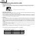
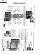
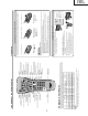
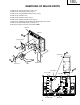
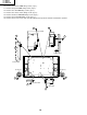
REMOVING OF MAJOR PARTS
1. Remove the stand cover fixing screw (1 pc.).
2. Remove the stand fixing screws (4 pcs.).
3. Remove the carrying handle fixing screws (4 pcs.).
4. Remove the terminal cover.
5. Remove the terminal screws (4 pcs.).
6. Remove the cabinet B fixing screws (9 pcs.).
7. Remove the cabinet B after opening from the direction of an arrow.
8. Remove the stand angle fixing screws (5 pcs.).
9. Disconnect all the connectors from all the PWBs.
Cabinet B
4
5
7
5
5
2
3
1
6
Carrying Handle
Cabinet A
Terminal Cover
Stand
Stand Cover
P6706
P6705
P6704
P6703
P6702
P6707
SC7701
SC7702
P7705
SC2004
SC2003
SC1201
SC2001
SC3402
SC4001
Stand Angle
Inverter PWB
Sub PWB
Power PWB
R/C, LED PWB
9
9
9
9
9
8
8
9
Main PWB