
Manual
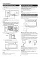

Part Names
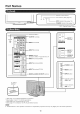
Remote control sensor _}_
[ [ ....... oPc ....... *(Seepage 18,) /
O O o ®
l [-- OPO indicator (See page 18,) |
POWER indicator (See page 12,)_
* QPO: Optical Picture Control
T [ml
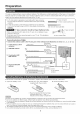
Antenna/Cabb in
_3Ftr:ll_ I OUTPUT termina,s
iqL
Zl® p--,NPUT,term'na'e
9,'1®it+_"PUT 2terminals
1r ]l" and INPUT 6)'4
I- INPUT 7 ten'ninal (HDMI)
J INPUT 6 terminal (HDMI)
DIGITAL AUDIO OUTPUT terminal
"1
INPUT 3
terminals
INPUT 5
terminal
(HDMI)
_ ERVICE
terminal
*2
_ POWER button
MENUI
[]_- MENU button
_,NPUT button
AC INPUT
terminal
_ l/_-'_ i Channel buttons
/l I (CHA/V)
-_II (VOL +/-)
'1 See page 11 for external equipment connection.
*2 See pages 12 and 17 for button operations.
'3 See page 8 for connecting the AC cord.
*4 See page 21 for details on the PC Audio Select function.
o The illustrations in this operation manual are for explanation purposes and may vary slightly from the actual operations.
10