
Manual


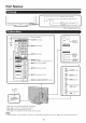

Part Names
Remote control sensor '}
[ r ........ oPc ...... * (See page18,) !
0 0 ® ®
l [-- OPC indicator (See page 18.) |
POWER indicator (See page 12.)_
* OPC: Optical Picture Control
AN_LE
Antenna/Cable in
_I-- OUTPUT terminals
L
_'!I® p--I.PUT I ter,ninale
9,!1®tP--_"PUT_tem*,a_e
_ --I.PUT6terminal(.DMI/
-- INPUT 4 terminal (PC IN)
DIGITAl. AUDIO OUTPUT terminal
i
INPUT 8
terminals
INPUT 5
terminal
(HDMI)
_ ERVICE
terminal
*2
powEM
(H_ POWER button
MENU I
HH-MENUbutton
INPUT I
_INPUT button
AC INPUT
terminal
__1 *3
"Ill'Oh....Ibuttons
_I_]l (CHA/V)
]/_/_i- Volume buttons
-_1 I (VOL +/-)
I
"1 See page 11 for external equipment connection,
*2 See pages 12 and 17 for button operations.
"3 See page 8 for connecting the AC cord.
*4 See page 21 for details on the PC Audio Select function.
o The illustrations in this operation manual are for explanation purposes and may vary slightS/from the actual operations.
10