PN-CD701 LCD MONITOR OPERATION MANUAL
Information on the Disposal of this Equipment and its Batteries IF YOU WISH TO DISPOSE OF THIS EQUIPMENT OR ITS BATTERIES, DO NOT USE THE ORDINARY WASTE BIN, AND DO NOT PUT THEM INTO A FIREPLACE! Used electrical and electronic equipment and batteries should always be collected and treated SEPARATELY in accordance with local law. Separate collection promotes an environment-friendly treatment, recycling of materials, and minimizing final disposal of waste.
IMPORTANT INFORMATION WARNING: TO REDUCE THE RISK OF FIRE OR ELECTRIC SHOCK, DO NOT EXPOSE THIS PRODUCT TO RAIN OR MOISTURE. CAUTION RISK OF ELECTRIC SHOCK DO NOT OPEN CAUTION: TO REDUCE THE RISK OF ELECTRIC SHOCK, DO NOT REMOVE COVER. NO USER-SERVICEABLE PARTS INSIDE. REFER SERVICING TO QUALIFIED SERVICE PERSONNEL.
DEAR SHARP CUSTOMER Thank you for your purchase of a SHARP LCD product. To ensure safety and many years of trouble-free operation of your product, please read the Safety Precautions carefully before using this product. SAFETY PRECAUTIONS Electricity is used to perform many useful functions, but it can also cause personal injuries and property damage if improperly handled. This product has been engineered and manufactured with the highest priority on safety.
SAFETY PRECAUTIONS (Continued) 19. Batteries — Incorrect use of batteries may cause the batteries to burst or ignite. A leaky battery may corrode the equipment, dirty your hands or spoil your clothing. In order to avoid these problems, make sure to observe the precautions below: • Use the specified batteries only. • Install the batteries with due attention to the plus (+) and minus (-) sides of the batteries according to the instructions in the compartment. • Do not mix old and new batteries.
TIPS AND SAFETY INSTRUCTIONS - The TFT color LCD panel used in this monitor is made with the application of high precision technology. However, there may be minute points on the screen where pixels never light or are permanently lit. Also, if the screen is viewed from an acute angle there may be uneven colors or brightness. Please note that these are not malfunctions but common phenomena of LCDs and will not affect the performance of the monitor.
MOUNTING PRECAUTIONS • This product is for use indoors. • A mounting bracket compliant with VESA specifications is required. • Since the monitor is heavy, consult your dealer before installing, removing or moving the monitor. • Mounting the monitor on the wall requires special expertise and the work must be performed by an authorized SHARP dealer. You should never attempt to perform any of this work yourself.
Contents IMPORTANT INFORMATION.............................................3 DEAR SHARP CUSTOMER...............................................4 SAFETY PRECAUTIONS...................................................4 TIPS AND SAFETY INSTRUCTIONS................................6 MOUNTING PRECAUTIONS.............................................7 Supplied Components......................................................9 System Requirements......................................................9 Part Names.......
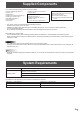
Supplied Components If any components are missing, please contact your dealer. Liquid Crystal Display Monitor: 1 Power cord HDMI cable: 1 USB Type C cable (26.2 feet [8 m]): 1 USB Type C extend cable: 1 CD-ROM (Utility Disk): 1 Setup Manual: 1 Touch pen: 1 USB A to B cable (for touch back): 1 Cable clamp: 1 Camera: 1 Knurled screw (M3): 2 USB A to B cable (for camera): 1 S/PDIF cable: 1 3.
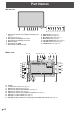
Part Names nFront view 1 2 3 4 5 6 7 1. USB port for external source (USB 3.0 compliant) (See page 13.) 2. Pen Tray (See page 17.) 3. LED indicator for USB Type C 1 source 4. LED indicator for USB Type C 2 source 5. Windows button 6. LED indicator for HDMI 7. LED indicator for Wireless LAN nRear view 15 35 8 2 8. 9. 10. 11. 12. 13. 14. 9 10 11 12 13 INPUT button (See page 21.) MENU button (See page 21.) MIC MUTE button (See page 21.) MUTE button (See page 21.) VOLUME DOWN button (See page 21.
Part Names 24. 25. 26. 27. 28. 29. 30. 31. 32. 33. 34. 35. 36. HDMI input terminal (See page 12.) Vents AC input terminal (See page 15.) Main power switch (See page 16.) USB Type C output terminal (See page 13.) USB port for storage expansion (USB 3.0 compliant) (See page 13.) LAN 2 terminal (See page 13.) Line out Audio output terminal (See page 12.) LAN 1 terminal (See page 13.) USB port for IoT sensor hub/USB devices (See page 12.) USB port for IoT sensor hub/USB devices (See page 12.
Connecting Peripheral Equipment nRear view 14 13 12 17 16 5 1 6 2 9 4 7 3 8 10 11 nFront view 15 Caution • Be sure to turn off the main power switch and disconnect the plug from the power outlet before connecting/ disconnecting cables. Also, read the manual of the equipment to be connected. • Be careful not to confuse the input terminal with the output terminal when connecting cables.
Connecting Peripheral Equipment 8. LAN 2 terminal • You can connect to the Internet by connecting a commercially available LAN cable between this terminal and a network. 9. LAN 1 terminal • By connecting this terminal to a network, you can connect an external device connected via USB to the network. 10. USB port for storage expansion (USB 3.0 compliant) • You can expand the storage used by the main system on this terminal by inserting a commercially available USB storage drive. 11.
Mounting an IoT sensor hub It is possible to mount an IoT sensor hub in the following position. 1. Attach the supplied IoT sensor hub mounting brackets (L/R) to the IoT sensor hub with the supplied IoT sensor hub screws (M3) (x2). 2. Fix the IoT sensor hub mounting brackets (L/R) to this monitor with supplied knurled screws (M3) (x2). * The IoT sensor hub mounting brackets fit into the recess of this monitor.
Connecting the Power Cord Caution • Use only the power cord supplied with the monitor. Main power switch 1. Turn off the main power switch. 2. Plug the power cord (supplied) into the AC input terminal. 3. Plug the power cord (supplied) into the power outlet. 1 1 AC input terminal 2 Power cord (Supplied) 3 For power outlet Preparing the Remote Control Unit Installing the batteries Remote control operation range 1. Place your finger on the part marked with the ▲, and then pull the cover off.
Turning Power On/Off nOperations after first power-on Caution • Turn on the monitor first before turning on the computer or playback device. • When switching the main power switch or the POWER button off and back on, always wait for at least 5 seconds. A short interval may result in a malfunction. • To keep the performance, put the monitor in the Power off state once a day. When the monitor is turned on for the first time after being shipped from the factory, the setting screen will be displayed.
Touch Pen Pen Eraser TIPS • Incorrect operation may result if your finger is too close to the tip of the pen. • Hold the touch pen with your bare hand. The screen will not respond if you wear a glove. • When multiple touch pens are used, touch positions and touch pen information (color, thickness, etc.) may become interchanged, and lines may break. - When touched simultaneously. - When touch pens are moved near each other. • Do not press the pen tip on other than the screen. This may cause malfunctioning.
Touch action Touch action Touch actions that can be used with this monitor differ according to operating system and application. The functions of touch actions are also different. For details, check operating system Help and the application’s support documentation. Operating system Windows 8.
Touch action Drag-and-drop Same action as drag-and-drop with a mouse. Touch the screen with your finger/touch pen and move without lifting. When you have finished the movement, lift your finger/ touch pen. nFinger actions Zoom Use in a screen that is capable of enlargement/reduction. Touch the screen with two fingers and move your fingers closer together to reduce the view, or apart to enlarge the view. Flicks Flick your finger/touch pen in the direction of the function you want to use.
Touch action Rotate Use this action in a screen that is capable of image rotation. Touch the center point of the rotation with one finger. While holding that finger still, move another finger in the desired direction of rotation. Move another finger in the desired direction of rotation With one finger touching TIPS • The screen may not respond correctly in the following cases: - Touch gesture is too quick. - The distance between the two points is too short. - The two points intersect.
Basic Operation Button Operation IoT accessories Operation 1. Camera module Camera module build with camera and Mic array. Which provide conference video function. Camera 6 5 4 3 2 IoT sensor Hub 1 1. POWER button See page 16. 2. VOLUME DOWN / UP buttons 2.1 No device connection Controlling this monitor volume up/down. 2.2 Device connection Controlling input device volume up/down. (Windows only. Must be connected with a USB cable.) 3. MUTE button 3.
Basic Operation Using the remote control unit (option) 1. POWER When “Operation Mode” is set to “Mode1” Press the POWER button to turn the power OFF (standby mode). 1 When “Operation Mode” is set to “Mode2” When you press the POWER button, the brightness will be reduced. 2. MUTE Turns off the volume temporarily. Press the MUTE button again to turn the sound back to the previous level. 3. VOLUME +/- (Volume adjustment) Pressing + or - displays the VOLUME menu. Press + or - to adjust the volume.
Menu Items Displaying the menu 1. Home screen The Home Screen is the default screen that users will see when they launch this monitor. Dashboard Button Displays the measurement results of the IoT sensor. (Temperature, Humidity, CO2 Levels, TVOC Levels, Motion) Home Button The Home button can be tapped at any time to get the user back to the home screen. Back Button 2. Action panel Input Button It will allow users to go back inside apps and also within the menu.
Menu Items 4. Instruction panel USB Type C instructions HDMI instructions Windows instructions Android instructions The instruction panel is broken down to different sections each with a different purpose. Wired Instructions The wired section will show you the status of the wired connections within each of the boxes. If the USB icon has a green status then that means that the connection is active.
Menu Items Main function in Action Panel Multi-input source This monitor can detect up to two external sources input. For Multi-input source, this monitor can also support PbyP display. The Action Panel can be controlled all panel setting which including OSD functions and input source switching. The below documentation links provide deeper dive into each button’s expanded content. 1.
Menu Items 2. Settings The Settings button will open up the Settings panel and allow the user to change device settings.
Menu Items Device Information OS/OS Version Model Hardware ID/Serial number Software License Open Source Library Admin Wireless LAN Name Choose A New Wallpaper Choose Install New Apps Choose Country Select Province / Region / State Select City Select Operation Mode Mode1 Power Saving Timeout: 5 mins (Standby mode) In Device Motion Sensor: Off Wake On LAN: Off IoT Sensor Hub Always On: Off Mode2 Power Saving Timeout: 5 mins (Brightness reduction) In Device Motion Sensor: On Wake On LAN: On IoT Se
Menu Items 2.1 Quick Settings In Quick Settings menu, it can be controlled Volume / Mic toggle / Brightness in both this monitor and external devices. 2.2 Display The Display settings will only affect external sources. The Display settings will not be applied to this monitor. 2.3 Network Network menu is setting the LAN connection between this monitor and external devices. E 28 2.
Network This monitor can be connected to a LAN. The connection requires a commercially available LAN cable (UTP cable, Category 5, straight through). Network (LAN) LAN 2 terminal Hub LAN cable (commercially available, straight) nSettings to connect to a LAN (LAN 2) 1. TCP/IP If your LAN has a DHCP server and you wish to obtain an address automatically, change this setting to DHCP. To set the address manually, set this to Manual. 1.1 IP Address If the TCP/IP is set to Manual, specify an IP address. 1.
Troubleshooting If you are experiencing any problem with your display, before calling for service, please review the following troubleshooting tips. There is no picture or sound. • The power LED is off. - Is power supplied to this monitor? - Is the power cord disconnected? (See page 15.) - Is the main power switch off? (See page 16.) • The power LED lights amber. - This monitor is in standby mode. Turn on the power. (See page 16.) Remote control does not work.
Specifications nProduct Specifications Model LCD component Max. resolution Max.
Specifications nDimensional Drawings Note that the values shown are approximate values. Unit: inch [mm] 63-15/16 [1623.5] 3-11/16 [94] 1-3/4 [44.5] 1-1/4 [31] 7-7/8 [200] 7-7/8 [200] 7-7/8 7-7/8 [200] [200] 19-11/16 [500.5] 38-7/16 [976.5] Opening height (34-1/4 [870]) Opening width (60-11/16 [1542]) 3-11/16 [93] 3-9/16 [90] Screw holes for mounting brackets When mounting the monitor, be sure to use a wall-mount bracket that complies with the VESA-compatible mounting method.
Specifications nCompatible signal timing Screen resolution VESA 640 × 480 800 × 600 Wide Vsync HDMI USB Type C 60Hz Yes Yes 72Hz Yes Yes 75Hz Yes Yes 56Hz - - 60Hz Yes Yes 72Hz Yes Yes 75Hz Yes Yes 848 × 480 60Hz - - 1024 × 768 60Hz Yes Yes 70Hz Yes Yes 75Hz Yes Yes 1152 × 864 75Hz Yes Yes 1280 × 768 60Hz - Yes 75Hz - Yes 1280 × 800 60Hz Yes Yes 1280 × 960 60Hz Yes Yes 1280 × 1024 60Hz Yes Yes 75Hz Yes Yes 1360 × 768 60Hz Yes Yes 1400 ×
Specifications nChannels that can be used in wireless LAN Standard Channel Frequency band (center frequency) EUROPEAN COUNTRIES IEEE802.11b/g/n 1-13ch 2412-2472MHz HONG KONG IEEE802.11ac/a/n 36/40/44/48ch 5180-5240MHz INDIA KUWAIT NEPAL OMAN PHILIPPINES RUSSIA SAUDI ARABIA SINGAPORE SOUTH AFRICA SRI LANKA THAILAND TURKEY UNITED ARAB EMIRATES VIETNAM AUSTRALIA IEEE802.11b/g/n 1-13ch 2412-2472MHz MALAYSIA IEEE802.
Intellectual Property Rights and Other Matters nInformation on the software license for this product Software composition The software included in this product is comprised of various software components whose individual copyrights are held by SHARP or by third parties.
Mounting Precautions (For SHARP dealers and service engineers) • When installing, removing or moving the monitor, ensure that this is carried out by at least 4 people. • Be sure to use a wall-mount bracket designed or designated for mounting the monitor. • This monitor is designed to be installed on a concrete wall or pillar. Reinforced work might be necessary for some materials such as plaster / thin plastic board / wood before starting installation.
PN-CD701 Me EN20A(2)