Installation Manual for RESU10H(Type-R) Compatible Inverter: SolarEdge, Fronius, Huawei LG Chem strongly advises to take due care in following LGC’s product installation manual. A warranty claim is invalid if damage is caused by human error, inconsistent with the installation manual. Version 1.
The information included in this manual is accurate at the time of publication. However, this manual is subject to change without prior notice. In addition, the concepts and installation instructions. Please note the image shown is for illustration purposes only. CAUTION After installation, the installer must explain the User Guide to the end-user. Jan.
Contents 1 Safety 5 1.1 Symbols.................................................................................................................... 5 1.2 Safety instructions ................................................................................................. 6 1.2.1 General safety precautions ........................................................................ 6 1.2.2 Battery handling guide .............................................................................. 6 1.2.
Contents 4 5 Commissioning 27 4.1 LED indicators ..................................................................................................... 27 4.2 Powering up the battery pack ............................................................................ 28 4.3 battery pack ............................................................................ 28 Troubleshooting 5.1 29 Troubleshooting ................................................................................................
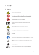
1 Safety 1.1 Symbols Caution, risk of electric shock Install the product out of reach of children. Read the instruction manual before starting installation and operation. Heavy weight may cause serious injury to the back. Do not dispose of the product with household wastes. Recyclable Disconnect the equipment before carrying out maintenance or repair. Observe precautions for handling electrostatic discharge sensitive devices.
Safety 1.2 Safety instructions For safety reasons, installers are responsible for familiarizing themselves with the contents of this document and all warnings before performing installation. 1.2.1 General safety precautions which can be extremely dangerous. All types of breakdown of the product may lead to a leakage of electrolyte or install in places where explosive gas or chemicals are present.
Safety Ëh /RhNojh0Cc,RNN3,j.h0Cc cc3L$I3hRaha3U Cah$whnN\n IC~30hU3acRNN3IYh b3aqC,3chLncjh$3hL 03h$wh\n IC~30hU3acRNN3IhRNIwY Ëh /RhNojh0 L <3hj@3hnNCjhCNhcn,@hs wch ch0aRUUCN<.h038oaLCN<.hCLU ,jCN<.h,njjCN< RahU3N3ja jCN
Safety 1.2.3 Response to emergency situations i@3h`2bmSz?h$ jj3awhU ,Gh,RLUaCc3chLnIjCUI3h$ jj3aC3cht@ jh a3h03cC
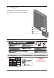
Safety 1.3 Warning label Warning labels and other relevant labels are attached to the inside of the battery pack. 1 2 4 3 1. Warning label 2. Product Label 3. Traceability Label 4.
Safety 1.4 Qualified personnel This guide and the tasks and procedures described herein are intended for use by skilled workers only. A skilled worker is defined as a trained and qualified electrician or installer who has all of the following skills and experience: Ëh Knowledge of the functional principles and operation of on-grid and off-grid (backup) systems. Ëh Knowledge of the dangers and risks associated with installing and using electrical devices and acceptable mitigation methods.
2 Product Introduction 2.1 Technical data 2.1.1 Dimensions and weight RESU10H P/N EVESPBO0100B0 Width 744 mm (29.3”) Height 907 mm (35.7”) Depth 206 mm (8.1”) Weight 1) 97 kg (214 lbs) 907 mm (35.7”) 1) A battery pack’s weight varies slightly. 744 mm (29.3”) 206 mm (8.
Product Introduction 2.1.2 Performance RESU10H Electrical Characteristics Total Energy Capacity Usable Energy Capacity 1) Battery Capacity Voltage Range Charge Discharge Absolute Max. Voltage Max. Charge/Discharge Current Max. Charge/Discharge Power2) Peak Power3) (only discharging) Peak Current (only discharging) Communication Interface DC Disconnect Connection Method User interface 9.8 kWh@25°C (77°F), 100% State of Energy 9.3 kWh 63 Ah 400 to 450 VDC 350 to 430 VDC 520VDC 11.9A@420V / 14.
Product Introduction 2.2 Feature • Compact Energy storage unit for domestic photovoltaic system compatibility • Aux Power and Protection Devices *Protection Devices - Inverter interface (between Battery Pack and Inverter) : Over Voltage, Over Current, External Short Circuit, Reverse Polarity, Inrush Current, Ground Fault , Over Temp.
3 Installation 3.1 3.1.1 Mechanical requirements Unboxing the package 1. Cut the packing tape and open the carton. 2. Pull out other items. Take them out and check if any item is missing. See Package items on section 3.1.
Installation 3. Remove the wall bracket guide pad & cushioning pad. 4. Remove the side pad. 5. Pull out the battery pack using handles and stand it up. (Lift handles are sold separately for this product.) CAUTION According to regional regulations, several people may be required for moving equipment.
Installation 3.1.2 Items in the package These items are included in the package. Battery pack 3.1.3 Wall bracket M6 wall mount bolts (2EA) Manual Installation locations Required : • There must be no highly ˜ammable or explosive materials nearby. • The ambient temperature should be within the range of 14 ~ 113°F (-10 ~ 45°C). • Battery pack must be installed on walls that are upright and can support battery weight. • Product can be installed indoors (ex.
Installation 3.1.4 Clearance • Minimum clearances for the left, right, top and bottom of the product is shown in the figure for the proper ventilation and installer convenience. 300mm (12") 300mm (12") 300mm (12") 300mm (12") Floor 3.1.5 Tools & safety gears required • Tools The following tools are required to install the battery pack : Precision screwdriver M6 Torque wrench Drill (Min. Diameter 10mm, 0.
Installation Saf gear f r It is recommended to wear the following safety gears when handling the battery pack. Insulated gloves Safety goggles Safety shoes NOTE RESU HV is heavy and challenging to lift. Lift handles are recommended.
Installation 3.1.6 Mounting bracket When installing the battery pack on a wall, make sure that the wall is capable of supporting the weight of the battery pack. To mount the battery pack on a wall, take the following steps : 1. Mark the location on the wall for the holes. 2. Drill holes for fasteners in the wall. 3. Drive the fasteners through the mounting bracket into the holes. Area 1 Area 2 Recommended diameter : 10mm(0.4") Min. Recommended length : 70mm(2.8") Min.
Installation 3.1.7 Appearance and dimension Appearance ly r r P r 907mm (35.7") 744mm (29.3") 206mm (8.1") 3.1.
Installation 3.1.9 Installing the battery pack CAUTION connecting the power cable to the battery pack. 1. Fix the lift handles to the hex-socket screws on the rear (marked position) of both left and right sides. 2. Mount the wall bracket to a wall. Tighten the screws, ensuring that they are horizontally driven into the wall. (Must be installed with recommended clearances(720mm[29"]) on the edge of the wall bracket as shown in the 3.
Installation 4. Tighten the two hex-socket screws enclosed and remove the lift handles. The nuts for these screws are welded to the battery pack chassis. Tighten to a torque of 5 Në m using the M6 torque wrench. 5. Press the two buttons and pull the two latches (marked position) on the rear side of the wiring box cover (hinged door). 6. Open the wiring box cover (about 2~10 degrees), and pull to remove it. CAUTION The wiring box cover is heavy. [approx. 1.6kg(3.5lb)] If dropped it may cause injury.
Installation 7. Loosen the screw (marked position), and remove the transparent protection cover. CAUTION If you lose or break a protection cover, that violates NEC Regulation. Transparent protection cover 8. Remove the cap on hole in the bottom side, and assemble the ¾" conduit plug. In the case outdoor, it must be sealed to comply “IP55” [ex) gasket, sealing foam, silicon, etc], where the battery pack installation is outdoor. 9. Connection Power / Communication cables, according to the labels marked.
Installation 3.2 Cable connection 1. See 3.2.1. for Power Cable specifications 3 2 1 a) Connect the ground wire to terminal 1. b) Connect the negative line of the power cable to terminal 2. c) Connect the positive line of the power cable to terminal 3. 2. See 3.2.1. for Communication Cable specifications 1234 56 At first, connect the ground wire to terminal 2. Then, make connections to the other terminals one after another. Install protection cover before turning on. 3.
Installation CAUTION Please turn on or off the switch by pushing the middle of the bar, where lever. It is forbidden to push either end side of the bar. Any improper use could damage the product. 5. Close the wiring box cover. Reattach battery over the two latches on the rear. 6. Hang the User Guide onto the latch on the rear of the battery. Connect/disconnect the wire to connector sequence 1. Make sure the circuit breaker off and the disconnect switch off.
Installation 3.2.1 Spring terminal blocks 1. Power terminal block Max cable length: 10m (35ft) Cable Type : 4~10 (8~12AWG) DC 600V insulated Pinning Phoenix Contact PCB Terminal Block SPT 5/3-V-7,5-ZB P/N : 1719325 (+) (-) GND 2. Communication terminal block (SELV) Max cable length: 10m (35ft) Cable Type : 0.2~1.
4 Commissioning 4.1 LED indicators The LED indicators on the front of the battery pack show its operational state as follows: LED Status Action Power on, Idle Charging Discharging Fault There are four LED indicators on the front of the battery packs to show its operating status. ON: This indicator stays on while the battery pack is ON. Charging: This stays on while the battery pack is charging. Discharging: This stays on while the battery pack is discharging.
Commissioning 4.2 Powering up the battery pack Put the battery pack in operation by taking the following steps : 1. Remove the wiring box cover. 2. Turn on the disconnect switch after installation battery pack. Make sure that the Circuit Breaker switch is in the OFF position (including Trip position) 3. Move the Circuit Breaker switch to the ON position. 4. Seconds after the Circuit Breaker switch is ON, 4 LEDs will be lit. 5.
5 Troubleshooting 5.1 Troubleshooting Check the indicators on the front to determine the state of the battery pack. A warning state is triggered when a condition, such as with voltage or temperature, is beyond design limitations. The battery pack’s BMS periodically reports its operating state to the inverter. When the battery pack falls outside prescribed limits, it enters a warning state. When a warning is reported, the inverter immediately stops operation.
Troubleshooting 5.1.1 Post-Installation Check List YES 1. Visual check if the wiring matches with the installation manual.(3.2 Cable connection) 2. The disconnect switch is ON. 3. The Circuit Breaker is ON. 4. The battery “ON” LED is ON 5. The inverter power is ON. 1) 6. The inverter has the latest firmware. 2) 7. The inverter recognizes the battery. 8. The battery can operate after installation is correctly done. 8-1. The AC grid is connected. 8-2. The Meter is installed. 8-3.
Troubleshooting If the battery LED is ON, but the battery is not charging or discharging 1. Update both the inverter and battery firmware version. Refer to the inverter's troubleshooting guide for instruction. 2. Check the inverter's setting for battery. Refer to the inverter's troubleshooting guide for the battery set-up instruction. 3. If the battery is recognized, inverter set up is correct. 4. If the issue persists, 4-1. Turn off the Circuit Breaker. 4-2. Turn off the disconnect switch. 4-3.
6 Uninstallation & Return 6.1 6.1.1 Return/replacement instructions Uninstallation from the wall 1. Switch OFF the Inverter before starting the uninstallation of the battery pack. 2. Press the two buttons and pull the two latches (marked position) on the rear. 3. Open the wiring box cover (about 2~10 degrees), and pull to remove it. 4. Switch off the circuit breaker and make sure that is in the OFF position. After that turn off the disconnect switch. CAUTION MUST follow the turn off procedure.
Uninstallation & Return 6. Check for voltage at power cable terminal. 7. Disconnect the communication cable from the communication port. 8. Disconnect the power cable from the terminal block. Disconnect the positive terminal (+) ǔ first, and next the negative terminal (−) Ǖ and finally ground terminal ǖ 9. Assemble transparent protection cover. Close the wiring box cover, and lock the ratchet. 10.
Uninstallation & Return 6.1.2 Contact information Damaged batteries are dangerous and must be handled with extreme caution. They seems to be damaged, contact LGC regional contact point or your distributor. Use the contacts below for technical assistance. These phone numbers are available only during business hours on weekdays.
Keep this manual for later use. © 2018 LG Chem ESS Battery Division LG Guanghwamun Building, 58, Saemunan-ro, Jongno-gu, Seoul, 03184, Korea http://www.lgesspartner.com http://www.lgchem.