5” LCD Color Monitor Sharp LL-153A Service Service Service Horizontal Frequency 30kHz –80kHz TABLE OF CONTENTS Description Page Description Page Table Of Contents.......……..……..........................…........1 6. Schematic……………....................................…17 Revision List.….............……..........................……......2 6.1 Main Board.……...……..........................................17 Important Safety Notice.…………....................……......3 6.2 Inverter Board..………..……................
15” LCD Color Monitor Sharp LL-153A Revision List Revision Date Revision History TPV Model A00 Dec-28-06 Initial Release T56CM5NJXXXWAJ 2
15” LCD Color Monitor Important Safety Notice Sharp LL-153A Proper service and repair is important to the safe, reliable operation of all AOC Company Equipment. The service procedures recommended by AOC and described in this service manual are effective methods of performing service operations. Some of these service operations require the use of tools specially designed for the purpose. The special tools should be used when and as recommended.
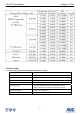
15” LCD Color Monitor Sharp LL-153A 1. Monitor Specifications Items Descriptions Driving system TFT Color LCD Type CPT CLAA150XP01Q Size 38cm(15.0") Pixel pitch 0.297mm(H) x 0.297mm(V) Viewable angle 140˚ (H) 125˚ (V) Response time (type) 8 ms for CPT panel Video R, G, B Analog input Digital input Sync. Type H/V TTL H-Frequency 24.
15” LCD Color Monitor Sharp LL-153A 2. LCD Monitor Description The LCD MONITOR will contain a main board, a power board and a keypad board which house the flat panel control logic, brightness control logic and DDC. The power board will provide AC to DC Inverter voltage to drive the backlight of panel and the main board chips each voltage. Monitor Block Diagram Flat Panel and CCFL Drive.
15” LCD Color Monitor Sharp LL-153A 3. Operating Instructions 3.1 General Instructions Press the power button to turn the monitor on or off. The other control buttons are located at front panel of the monitor. By changing these settings, the picture can be adjusted to your personal preferences. • The power cord should be connected. • Connect the video cable from the monitor to the video card. • Press the power button to turn on the monitor position. The power indicator will light up. 3.
15” LCD Color Monitor Sharp LL-153A 3.3 Adjusting the Picture 1. Press the MENU-button to activate the OSD window. 2. Press < or > to select the desired function. 3. Press the / MODE -button to select the function that you want to adjust. 4. Press < or > to change the settings of the current function. 5. To exit and save, select the exit function, or leave the monitor alone for 10 seconds. If you want to adjust any other function, repeat steps 2-4.
15” LCD Color Monitor Sharp LL-153A Information Show the model, the S/N and the Usage time. Off The off timer is off On The off timer is on 4. Input/Output Specification 4.1 Input Signal Connector D-SUB connector Pin No. Description Pin No. Description 1. Red Video 9. +5V Supply 2. Green Video 10. GND 3. Blue Video 11. NC 4. NC 12. DDC-Serial Data 5. GND 13. H-Sync 6. Red Ground 14. V-Sync 7. Green Ground 15. DDC-Serial Clock 8.
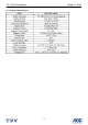
15” LCD Color Monitor Sharp LL-153A 4.2 Factory Preset Display Modes 4.3 Power Supply The power supply should be integrated to the monitor housing. A/C Line voltage range : 100 V ~ 240 V A/C Line frequency range : 50 ± 3Hz, 60 ± 3Hz Current : 1.5A max at 100V; 0.8A max at 240 V Peak surge current : < 55A peak at 240 VAC and cold starting Leakage current : < 3.
15” LCD Color Monitor Sharp LL-153A 4.4 Panel Specification 4.4.
15” LCD Color Monitor Sharp LL-153A 4.4.2 Optical Characteristics 4.4.
15” LCD Color Monitor Sharp LL-153A Back- Light Unit 12
15” LCD Color Monitor Sharp LL-153A 5. Block Diagram 5.
15” LCD Color Monitor Sharp LL-153A 1) MCU initializes. 2) Is the EPROM blank? 3) Program the EPROM by default values. 4) Get the PWM value of brightness from EPROM. 5) Is the power key pressed? 6) Clear all global flags. 7) Are the AUTO and SELECT keys pressed? 8) Enter factory mode. 9) Save the power key status into EPROM. Turn on the LED and set it to green color. Scalar initializes. 10) In standby mode? 11) Update the lifetime of back light.
” LCD Color Monitor Sharp LL-153A 5.2 Electrical Block Diagram 5.2.1 Main Board LCD Interface Flash memory Scalar TSUM13AK (Include:ADC,OSD,MCU etc.) EPR_SDA EPR_SCL OSD Control Interface (Key pad) RXD TXD RGB H-SYNC V-SYNC D-Sub Connector EEPROM 24C16 DB15_SDA DB15_SCL EEPROM 24C02 15 Crystal 14.
15” LCD Color Monitor Sharp LL-153A 5.2.
15” LCD Color Monitor Sharp LL-153A 6. Schematic 6.1 Main Board TSUM13AK XGA/SXGA B3 SCHEMATIC LVDS OUTPUT B4 RIN GNDR GIN GNDG SOG BIN GNDB HSY NC VSY NC DDCA_SDA DDCA_SCL DET_VGA +5V +5V RIN GNDR GIN GNDG SOG BIN GNDB HSY NC VSY NC DDCA_SDA DDCA_SCL DET_VGA VCC1.8 +3V3 +5V +12V VCC1.8 DDC_WP DDC_WP +3V3 +5V +12V 3.INPUT B5 PA[0..7] PA[0..7] PA[0..7] +3V3 PA[12..13] PA[12..13] PA[12..13] +12V PB[12..21] PB[12..21] PB[12..21] +3V3 VLCD VCC1.
15” LCD Color Monitor Sharp LL-153A +3V3 +3V3 +5V Q602 AO3401L (3,4,5) AIC1084-18PM TO-263 layout together L602 22uH 3 2 PGATE C610 + D602 1 C604 100uF/25V 0.1uF C609 220uF/25V + U601 LM3485 7 C613 0.001uF 6 5 VIN PGATE VIN VOUT VCC1.8 (4) ADJ C602 47uF/25V + 47uF/25V C603 0.1uF 3 N.C 2 PWGND AGND ADJ 1 + 2 C614 0.001uF 4 FB C601 C612 0.001uF SSM54 8 R606 33K 1/16W R605 22 1/16W VCC1.8 U602 3 R607 1 ISENSE 33K C611 0.
Sharp LL-153A CN405 R440 1/16W FB409 0 1/16W FB411 0 1/16W FB412 0 1/16W 56 1/16W C432 0.047uF R435 56 1/16W C433 0.047uF R436 56 1/16W C434 0.047uF R437 470 1/16W C435 0.001uF R441 100 1/16W C436 0.047uF R442 100 1/16W C437 0.047uF R443 100 1/16W C438 0.047uF RIN (4) GIN (4) BIN (4) SOG (4) GNDR (4) GNDG (4) GNDB (4) +5V PC5V D405 BAV99 ESD_5V 1 C439 0.1uF R470 D404 BAV99 R434 C440 0.1uF C441 0.1uF +5V 1 UDZS5.
15” LCD Color Monitor VDVI Sharp LL-153A VMPLL VPLL AVDD VDDP VDDC +5V 0.
15” LCD Color Monitor (4) PA[0..7] Sharp LL-153A PA[0..7] PA0 PA1 PA2 PA3 PA4 PA5 PA6 PA7 LVACKP LVACKM LVA2P LVA2M LVA1P LVA1M LVA0P LVA0M +3V3 +3V3 (2,3,4) R728 (4) PA[12..13] PA12 PA13 2.2K LVA3P LVA3M 1/16W LVDS_TEST R729 NC (4) PB[12..21] PB[12..
15” LCD Color Monitor Sharp LL-153A 6.2 Inverter Board RJ801 0 1/8W RJ802 0 1/8W PT801 80GL19T-36-DN 5 7 RJ804 0 1/8W CN801 2 R836 1K 1/10W 3 4 R819 1/8W 15 2 R821 100K 1000P/50V 1 33G8021-2D-U R822 3M / 1/2W 1/10W 2 5 1 1 2 N.C R823 75K 1/10W D801 BAV70 1/10W D809 LL4148WP N.C C829 0.1uF/50V 1/8W Thursday , May 04, 2006 Sheet 2 of 2 R845 R846 R847 R835 1M 1/10W 1M 1/10W 1M 1/10W 1M 1/10W C824 0.1uF/25V C830 0.1uF/25V R841 1/10W 1% 430 C810 470PF/50V C832 C831 0.
15” LCD Color Monitor Sharp LL-153A 6.3 Adapter Board 2 R907 680K 1/4W R910 430K 1/4W R908 680K 1/4W C902 0.001uF/250V ZD906 NC ! 4 R918 10 1/4W R919 10K 1/8W C917 0.001uF ! C915 0.1uF/25V RLZ22B t ! R915 100 1/8W ! FUSE ! R913 4.7K 1/8W C916 0.1uF/25V ZD903 PTZ7.5B 3.5uH +5V C912 1000uF/25V + C911 470UF/25V C910 0.1uF/25V F801 + C908 NC NC CN903 3 2 1 0.001uF/250V FB901 BEAD CONN(NC) R927 100 1/4W R904 0.68Ω 2W ZD904 RLZ12B 1 ZD902 RLZ5.1B R920 33K 1/8W R921 3.
15” LCD Color Monitor Sharp LL-153A 6.
15” LCD Color Monitor Sharp LL-153A 7. PCB Layout 7.
15” LCD Color Monitor Sharp LL-153A 7.
15” LCD Color Monitor Sharp LL-153A 7.
15” LCD Color Monitor Sharp LL-153A 7.4 Key Board 8. Maintainability 8.1 Equipments and Tools Requirement 1. Voltmeter.150 2. Oscilloscope. 3. Pattern Generator. 4. DDC Tool with an IBM Compatible Computer. 5. Alignment Tool. 6. LCD Color Analyzer. 7. Service Manual. 8. User Manual.
15” LCD Color Monitor Sharp LL-153A 8.2 Trouble Shooting 8.2.1 MAIN BOARD NO SCREEN APPEAR Measured CN701 pin5,6 = 12 V? Measured CN701 pin 9,10= 5V? Measured U702 pin 2= 3.3V? Measured U602 pin 2= 1.8V? Measured CN402 pin 1/2 = 5V? Measured CN402 pin 3/4 = 3.3V? NG Check Correspondent component. Is there any shortage or cold solder? Yes .
15” LCD Color Monitor Sharp LL-153A 2.PANEL POWER CIRCUIT Check R731 should have response from 0V to 5V NG , no transition Check the PPWR panel power relative circuit, Mea When we switch the power switch from on to off Q704(pin2) In normal operation, when LED =green, R731 should =0 v, OK Yes Measured the Q706 pin 3= 5 V? OK Replace Q602 ( N-MOS, A03401) NG, no Voltage OK 3.
15” LCD Color Monitor Sharp LL-153A 4. U4-DATA OUTPUT Measured DCLK(pin 65,66 from U401) NG , no transition DVS, DHS (pin 63,64 from U401 ) Is the waveform ok? Replace TSUM13AK (U401) or DCLK around 48 MHZ , DVS=60.09Hz , DHS around 80 replace Main board. KHz ?(refer to input signal=640x480@60 Hz 31k, and LED is Green) OK Check TSUM13AK(U401) If Main Board being replace, please Signal output (PIN105-114, 118-127) do the DDC – content reprogrammed Is the waveform ok ? OK OK 8.2.
15” LCD Color Monitor Sharp LL-153A 8.2.3 Power/Inverter Board 1.
15” LCD Color Monitor Sharp LL-153A 2.
15” LCD Color Monitor Sharp LL-153A 9. White-Balance, Luminance Adjustment Approximately 30 minutes should be allowed for warm up before proceeding White-Balance adjustment. 1. How to do the CA210 MEM. Channel setting A. Reference to CA210 user guide B. Use “ SC” key and “ NEXT” key to modify x, y, Y value and use “ID” key to modify the TEXT description Following is the procedure to do white-balance adjust: 2. Setting the color temp. you want A. MEM.CHANNEL 1 (9300K color): 9300K color temp.
15” LCD Color Monitor Sharp LL-153A 5. Adjust the GREEN of color1 on factory window until CA210 indicator reached the value G=100 6. Adjust the BLUE of color1 on factory window until CA210 indicator reached the value B=100 7. Repeat above procedure (item 4,5) until CA210 R/G value meet the tolerance =100±5 8. Repeat above procedure (item 6) until CA210 B value meet the tolerance =126±5 C. Adjust 6500K color-temperature 1. Switch the CA210 to STD (with press “MODE” button) 2. Switch the MEM.
15” LCD Color Monitor Sharp LL-153A 10.
15” LCD Color Monitor Sharp LL-153A 11. BOM List T56CM5NJXXXWAJ Location Part No.
15” LCD Color Monitor Sharp LL-153A XN01C M1G1730 6120 M3*6 XN01A Q1G 330 6120 SCREW M3X6MM XN01A Q1G 330 10120 SCREW XN01A Q1G1030 SCREW 3X8 NI 8120 705GP503 1A SH PAPER PAD ASS'Y 750GLC50P1Q13N PANEL LCD CLAA150XP01Q 0 XN01A AM1G1740 10120 SCREW D-SUB J02G 247 SH SCREW J15G0030 MAIN FRAME 1 J44GP504624 1A CARTON J45G8088609SH1 EPE BAG FOR BASE J52G8025 11823 INSULATE SHEET AUPC560KB8SMTP AUPC BOARD FOR SMT 12G 408 10 THERMAL PAD CN204 33G3278 WAFER 3P PLUG 2.
15” LCD Color Monitor Sharp LL-153A 715G1144 3 SH PCB SMTC6CM5XWJ1 MAIN BOARD CN404 33G801714H H PIN2*7 CN701 33G8027 12 WAFER 2*6P 2.0MM R/A CN403 33G8027 16 WAFER 16PIN 2.0MM DIP CN101 33G8027 24 H PIN 24P 2.
15” LCD Color Monitor Sharp LL-153A FB412 61G0603000 CHIPR 0OHM +-5% 1/10W R419 61G0603000 CHIPR 0OHM +-5% 1/10W R421 61G0603000 CHIPR 0OHM +-5% 1/10W R480 61G0603000 CHIPR 0OHM +-5% 1/10W R493 61G0603000 CHIPR 0OHM +-5% 1/10W R494 61G0603000 CHIPR 0OHM +-5% 1/10W R702 61G0603000 CHIPR 0OHM +-5% 1/10W R409 61G0603101 CHIPR 100OHM +-5% 1/10W R414 61G0603101 CHIPR 100OHM +-5% 1/10W R427 61G0603101 CHIPR 100OHM +-5% 1/10W R428 61G0603101 CHIPR 100OHM +-5% 1/10W R429 61G06031
15” LCD Color Monitor Sharp LL-153A R426 61G0603103 CHIPR 10KOHM+-5% 1/10W R458 61G0603103 CHIPR 10KOHM+-5% 1/10W R474 61G0603103 CHIPR 10KOHM+-5% 1/10W R475 61G0603103 CHIPR 10KOHM+-5% 1/10W R476 61G0603103 CHIPR 10KOHM+-5% 1/10W R477 61G0603103 CHIPR 10KOHM+-5% 1/10W R479 61G0603103 CHIPR 10KOHM+-5% 1/10W R488 61G0603103 CHIPR 10KOHM+-5% 1/10W R490 61G0603103 CHIPR 10KOHM+-5% 1/10W R491 61G0603103 CHIPR 10KOHM+-5% 1/10W R492 61G0603103 CHIPR 10KOHM+-5% 1/10W R495 61G060
15” LCD Color Monitor Sharp LL-153A R440 61G0603750 CHIPR 75OHM+-5%1/10W ZD404 61G0805000 RST CHIP MAX F601 61G1206000 CHIP resistors 1/3W F602 61G1206000 CHIP resistors 1/3W R485 61G1206000 CHIP resistors 1/3W R732 61G1206102 CHIP 1K OHM 5% 1/8W C435 65G0603102 32 CHIP 1000PF 50 X7R C611 65G0603102 32 CHIP 1000PF 50 X7R C612 65G0603102 32 CHIP 1000PF 50 X7R C613 65G0603102 32 CHIP 1000PF 50 X7R C614 65G0603102 32 CHIP 1000PF 50 X7R C113 65G0603104 32 CHIP 0.
15” LCD Color Monitor Sharp LL-153A C603 65G0603104 32 CHIP 0.1UF 50V X7R C604 65G0603104 32 CHIP 0.1UF 50V X7R C701 65G0603104 32 CHIP 0.1UF 50V X7R C706 65G0603104 32 CHIP 0.1UF 50V X7R C709 65G0603104 32 CHIP 0.1UF 50V X7R C711 65G0603104 32 CHIP 0.1UF 50V X7R C720 65G0603104 32 CHIP 0.
15” LCD Color Monitor Sharp LL-153A ZD408 93G 39S 34 T ZENER DIODE UDZS5.6B ZD409 93G 39S 34 T ZENER DIODE UDZS5.6B ZD410 93G 39S 34 T ZENER DIODE UDZS5.6B ZD411 93G 39S 34 T ZENER DIODE UDZS5.6B ZD412 93G 39S 34 T ZENER DIODE UDZS5.6B ZD413 93G 39S 34 T ZENER DIODE UDZS5.6B ZD414 93G 39S 34 T ZENER DIODE UDZS5.
15” LCD Color Monitor Sharp LL-153A NR901 61G 58080 WT NTCR C903 63G 10747410S 0.47UF +-10% 250VAC C816 65G 3J2206ET 22PF 5% 3KV TDK C817 65G 3J5096ET 5PF 5% SL 3KV C901 65G306M1022BM Y1.CAP.001UF 250VAC MURA C902 65G306M1022BM Y1.CAP.001UF 250VAC MURA C921 65G306M1022BM Y1.CAP.
15” LCD Color Monitor Sharp LL-153A Q804 57G 759 2 TRANSISTOR RK7002 SOT-3 Q806 57G 759 2 TRANSISTOR RK7002 SOT-3 Q807 57G 759 2 TRANSISTOR RK7002 SOT-3 Q808 57G 759 2 TRANSISTOR RK7002 SOT-3 Q805 57G 763 14 AM9945N-T1-PF R839 61G0805000 RST CHIP MAX 0R05 1/8W R844 61G0805000 RST CHIP MAX 0R05 1/8W R925 61G0805000 RST CHIP MAX 0R05 1/8W RJ824 61G0805000 RST CHIP MAX 0R05 1/8W R836 61G0805100 RST CHIP 10R 1/8W 5% R837 61G0805100 RST CHIP 10R 1/8W 5% R826 61G080
15” LCD Color Monitor Sharp LL-153A R817 61G0805360 2F RST CHIPR 36 KOHM +-1% 1 R843 61G0805471 RST CHIP 470R 1/8W 5% R913 61G0805472 RST CHIP 4K7 1/8W 5% R811 61G0805473 RST CHIP 47K 1/8W 5% R827 61G0805510 1F RST CHIPR 5.
15” LCD Color Monitor Sharp LL-153A C915 65G0805104 22 CHIP 0.1UF 25VX7R 0805 C916 65G0805104 22 CHIP 0.1UF 25VX7R 0805 C801 65G0805104 32 CHIP 0.1UF 50V X7R 0805 C820 65G0805104 32 CHIP 0.1UF 50V X7R 0805 C821 65G0805104 32 CHIP 0.1UF 50V X7R 0805 C822 65G0805104 32 CHIP 0.1UF 50V X7R 0805 C806 65G0805105 22 CHIP 1UF 25V X7R 0805 C918 65G0805105 22 CHIP 1UF 25V X7R 0805 C804 65G0805155 A2 1.
15” LCD Color Monitor Sharp LL-153A Q903 6G 31502 1.5MM RIVET R904 6G 31502 1.5MM RIVET T901 6G 31502 1.5MM RIVET IC903 56G 158 10 R928 61G 20022152T 220OHM 1% 1/4W R822 61G212Y305 KT MGFR 3M OHM +-5% 1/2W C930 65G 1500PF +/-10% 1KV Y5P C922 67G 2152207NT 22UF/50V F901 84G 55 7W 250V/3.15A FUSE F902 84G 55 7W 250V/3.