LL-S242A-W LL-P202V LCD MONITOR OPERATION MANUAL
IMPORTANT: To aid reporting in case of loss or theft, please record the product’s model and serial numbers in the space provided. The numbers are located in the rear of the product. Model No.: Serial No.: U.S.A. ONLY This device complies with Part 15 of the FCC Rules. Operation is subject to the following two conditions: (1) This device may not cause harmful interference, and (2) this device must accept any interference received, including interference that may cause undesired operation.
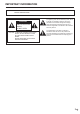
IMPORTANT INFORMATION WARNING: TO REDUCE THE RISK OF FIRE OR ELECTRIC SHOCK, DO NOT EXPOSE THIS PRODUCT TO RAIN OR MOISTURE. CAUTION RISK OF ELECTRIC SHOCK DO NOT OPEN CAUTION: TO REDUCE THE RISK OF ELECTRIC SHOCK, DO NOT REMOVE COVER. NO USER-SERVICEABLE PARTS INSIDE. REFER SERVICING TO QUALIFIED SERVICE PERSONNEL.
DEAR SHARP CUSTOMER Thank you for your purchase of a SHARP LCD product. To ensure safety and many years of trouble-free operation of your product, please read the Safety Precautions carefully before using this product. SAFETY PRECAUTIONS Electricity is used to perform many useful functions, but it can also cause personal injuries and property damage if improperly handled. This product has been engineered and manufactured with the highest priority on safety.
SAFETY PRECAUTIONS (Continued) 19. Usage of the monitor must not be accompanied by fatal risks or dangers that, could lead directly to death, personal injury, severe physical damage or other loss, including nuclear reaction control in nuclear facility, medical life support system, and missile launch control in a weapon system. 20. Do not touch the parts of the product or the AC adapter that become hot for long periods of time. Doing so may result in low-temperature burns.
TIPS AND SAFETY INSTRUCTIONS - The TFT color LCD panel used in this monitor is made with the application of high precision technology. However, there may be minute points on the screen where pixels never light or are permanently lit. Also, if the screen is viewed from an acute angle there may be uneven colors or brightness. Please note that these are not malfunctions but common phenomena of LCDs and will not affect the performance of the monitor.
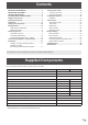
Contents IMPORTANT INFORMATION.............................................3 DEAR SHARP CUSTOMER...............................................4 SAFETY PRECAUTIONS...................................................4 TIPS AND SAFETY INSTRUCTIONS................................6 Supplied Components......................................................7 System Requirements......................................................8 Part Names........................................................................
System Requirements nTouch panel To use the touch panel, the monitor must be connected to a computer using a USB cable. Touch panel operating conditions are as described below. Computer PC/AT compatible computer with a USB 1.1 port and able to output a resolution of 1920 x 1080. Windows 8.1 (32-bit or 64-bit version), Windows 8 (32-bit or 64-bit version), OS Windows 7 (32-bit or 64-bit version), Windows Vista (32-bit or 64-bit version) • Windows 7 or later is recommended for touch action.
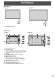
Part Names nFront view LL-S242A-W LL-P202V 1 1. Power LED (See page 18.) 1 nRear view LL-P202V 3 2 LL-S242A-W 1 3 3 2 1 3 6 6 7 7 8 8 9 4 10 11 9 4 10 11 5 5 1. VESA holes (See page 31.) 2. Anti-theft hole ( ) Allows the monitor to be secured using a commercially available anti-theft lock. The anti-theft hole is compatible with Kensington’s MicroSaver security system. 3. Speakers 4. Power/Menu button (See page 18, page 24.) 5. Cable clamp (See page 10.) 6.
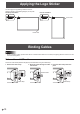
Applying the Logo Sticker You can apply the supplied logo sticker to the unit. Attach as shown in the following diagram, as required. Landscape orientation Portrait orientation Power LED Power LED Binding Cables Caution • When connecting cables, spread a soft cloth on a stable level surface such as a desk, and gently place the monitor on it with the screen facing down. Video cable and USB cable Secure the video cable (HDMI or DisplayPort) and USB cable using the cable clamp. 1.
Binding Cables Digitizer pen cable You can secure the digitizer pen cable using the supplied clamper and fixing screw. 1. Pass the digitizer pen cable through the ring of the clamper. 2. Attach the clamper using the fixing screw. Clamper Fixing screw Digitizer pen cable Connecting Devices Caution • Be sure to turn off the power and disconnect the plug from the power outlet before connecting/disconnecting cables. Also, read the manual of the equipment to be connected.
Connecting Devices TIPS • The length of the signal cables or surrounding environment may affect the image quality. • The video from the terminal that has signal input is displayed. In this state, even if a signal is input from the other terminal, the display is not switched. To switch the display, use [Input Select] on the menu screen. (See page 25.
Connecting the Monitor to a Power Source Caution • Use only the AC adapter and power cord supplied with the monitor. 1. Connect the monitor to the power outlet using the supplied AC adapter and power cord. Back of monitor For power outlet AC adapter connection terminal Core restrainer AC adapter (Supplied) Power cord (Supplied) AC adapter core 2. Push the AC adapter core into the core restrainer.
Installation You can install the touch display for each monitor in the following positions. Installation position LL-S242A-W LL-P202V Rack stand Yes No Variable stand No Yes Pen writing position No Yes Horizontal position Yes Yes Standing position 3. Place the monitor in the standing position, and adjust the angle of the stand. Hold the display with one hand so that it does not fall over, hold the rear leg of the stand with your other hand, and adjust the angle of the stand.
Installation 3. Peel off the adhesive tape securing the support to the back side. nLL-S242A-W Placement on the rack stand Place the unit on the supplied rack stand. 1. Attach the back of the stand to the front. Place the front and back sides together, and attach the hinge. Tape Back Front hinge part Front Support Back 4. Fold down the support, inserting the tabs into the holes on the front side. Back hinge part 5. Position the stand. Tape Front Back Support 6.
Installation Disassembling the rack stand Portrait orientation Remove the monitor from the rack stand before disassembling the stand. Caution • After removing the monitor from the rack stand, store the stand so that the screws will not be lost. 1. Remove the screws and remove the monitor. Remove fixing screws Run the cables along the hollow on the front side and out between the legs of the back side. 7. Secure the monitor to the stand using the two fixing screws.
Installing on a table (Pen writing position/Horizontal position) Remove the monitor from the stand and place face-down on a table or other level surface. Horizontal position Place the monitor on a table or other level surface. Caution • When using the monitor horizontally, use the horizontal tab in the upright position. 1. Lift up the two tabs on the back of the monitor. Caution • Do not exert a large amount of force on the monitor from above. Doing so may damage the flap.
Turning Power On/Off Turning on the power Turning off the power 1. Press the POWER button. 1. Turn off the PC. 2. Depress the POWER button for around 2 seconds. POWER button POWER button Press Power LED The power LED turns on. Caution Status of the monitor Green lit Signal input Orange lit No signal input Alternately flashing red and Abnormal temperature green Caution • When switching the POWER button off and back on, always wait for an interval of at least 5 seconds.
Installing the Software To use the touch panel or the supplied digitizer pen, the required software must be installed for the operating system of the connected computer. The required software is given below. LL-S242A-W LL-P202V Windows 8.1 / 8 Windows 7 Windows Vista Windows 8.1 / 8 Windows 7 Windows Vista Digitizer pen utility No No No Yes Yes No Touch panel driver for Windows Vista No No Yes No No Yes Installation Install the software from the suppolied CD-ROM.
Touch Actions Touch action modes TIPS There are three touch action modes: finger/pen mode, penonly mode, and finger-only mode. These modes can be changed on the menu screen. The monitor is set to finger/pen mode when shipped. Caution • Use the supplied pen (digitizer pen or touch pen) in pen mode. • In Windows 7, if the checkmark has been removed from “Enable multi-touch gestures and inking” in “Pen and touch” in Control Panel, select the checkbox.
Touch Action Drag-and-drop Touch the screen with your finger/pen and move without lifting. When you have finished the movement, lift your finger/pen. nFinger actions Zoom While touching the screen with two fingers, move them closer together and farther apart. Slide to pan With your finger/pen touching the screen, move it up and down to scroll the screen. Flicks Move your finger/pen in a flicking motion.
Touch Action Digitizer pen The LL-P202V monitor supports a digitizer pen. To use the digitizer pen, the utility software must be installed. (See page 19.) nDigitizer pen actions Button operations Function button 2 Pen tip TIPS • The shortcut launcher is not displayed on the Windows 8.1/8 Start screen or on the Windows Store screen. • When the digitizer pen is connected, digitizer pen actions are enabled and touch pen actions are disabled. To use touch pen actions, disconnect the digitizer pen.
Touch Action nSpare pen tip storage 1. Unscrew the pen tip cover and remove it. The pen stand features a pen tip storage area where you can store spare pen tips. TIPS • Spare pen tips are not stored in the stand at the time of purchase. Store the spare pen tips in the pen stand to make sure you do not lose them. 1. Remove the spare pen tip storage cap. 2. Pull out the pen tip. Cap Pen tip storage 2. Insert the spare pen tips into the holes in the pen tip storage. 3.
Monitor Settings Menu operations The monitor settings are configured by displaying the menu screen. The operations on this page are the basic operations. 4. Touch [Exit] or press the MENU button. The menu screen disappears. Caution • Do not turn off the power while the menu screen is displayed. Doing so may initialize the settings. • While the menu screen is displayed, touch actions are not possible other than those for the menu screen.
Monitor Settings Menu functions Exit Setup Input Select Volume Finger-only Pen-only mode mode Finger/pen mode Touch mode selection Touch mode selection These icons switch the touch action mode. A ( ) mark is displayed at the top of the icon for the selected mode. The mode can be checked using the touch mark located on the right-side of the screen. (See pages 26, 28) On the LL-P202V, the icon pen design varies when the digitizer pen is connected.
Monitor Settings SETUP Menu Details Menu Position Position When the monitor is used in portrait orientation (power/menu button on the top), this icon moves the display position of the menu screen to the bottom of the screen. Mode Mode Normal This mode is suited to normal PC screen display. Pen Writing This mode is suited to pen writing position. Game This mode is suited to video games. Multimedia This mode is suited to video playback. User The user can adjust the image quality.
Monitor Settings Prohibiting operations (operation lock) This function makes it possible to prohibit operations to turn the power off and to prohibit touch action on the screen. If an operation is attempted when the monitor is locked, a key mark is displayed for around 5 seconds. Operation lock is enabled. A key mark is displayed on the screen and it disappears after around 5 seconds. The key mark can be set to always be displayed. (See page 26.
Monitor Settings Monitor status indicators n Disabling operation lock 1. Press the MENU button. The menu screen is displayed. The status is displayed on the right-side of the screen. Touch Mark MENU button Press 2. While touching [Input Select], touch [Finger-only mode] for at least 1 second. Key Mark Touch Mark The touch mark displays the current touch action mode. Finger/pen mode This mark is displayed during finger/pen mode. appears.
Troubleshooting If you are experiencing any problem with your display, before calling for service, please review the following troubleshooting tips. There is no picture or sound. • Are the AC adapter and power cord connected correctly? (See page 13.) • Is the power on? (See page 18.) There is a picture but no sound. • Make sure the volume is not set to minimum. (See page 25.) • Is the sound muted? (See page 25.
Specifications nProduct Specifications Model LCD component LL-S242A-W (white) LL-P202V 24” Class [23-5/8” (60.0 cm) 20” Class [19-1/2” (49.5 cm) diagonal] TFT LCD diagonal] TFT LCD Max. resolution (pixels) 1920 x 1080 Max. colors Approx. 16.70 million colors Approx. 16.77 million colors Pixel pitch 0.272 mm (H) x 0.272 mm (V) 0.225mm (H) x 0.225 mm (V) Viewing angle 178° right/left/up/down (contrast ratio ≥ 10) Screen active area inch (mm) 20-1/2 x 11-9/16 (521.3 x 293.
Specifications nDimensional Drawings Note that the values shown are approximate values. LL-S242A-W VESA holes * 1-1/8 [28.7] (excluding protrusions) 1-15/16 1-15/16 [50] [50] 22-5/16 [566.4] Unit: inch [mm] 1-15/16 1-15/16 [50] [50] 13-5/16 [338.3] Screen display size (11-9/16 [293.2]) Screen display size (20-1/2 [521.3]) LL-P202V VESA holes * 1-15/16 1-15/16 [50] [50] 1 [25.2] (excluding protrusions) Unit: inch [mm] 18-1/4 [463.8] 1-15/16 1-15/16 [50] [50] 10-13/16 [274.
Specifications 11-5/16 [287.9] 1-1/2 [38.2]* 1-1/8 [28.7]* 4-9/16 [116.5] LL-P202V 75° 20° 12-11/16 [323] 5-1/2 [137.6] (20 degrees) (75 degrees) * Height of bottom of screen from table surface 2-3/8 [60.7] 9/16 [13.9] nPen writing position (LL-P202V) 10-13/16 [275.3] nSupported frequency Resolution Frame rate 640×480 60Hz VGA 800×600 60Hz SVGA 1024×768 60Hz XGA 720×480p 59.94/60Hz 1280×720p 50/59.94/60Hz 1920×1080p 50/59.
Specifications nHDMI input terminal (HDMITM Connector) No. Function pins nDisplayPort input terminal pins (DisplayPort 20 pin) No. Function No. Function No. Function 1 TMDS data 2+ 11 TMDS clock shield 1 MainLane 3- 11 Gnd 2 TMDS data 2 shield 12 TMDS clock- 2 Gnd 12 MainLane 0+ 3 TMDS data 2- 13 CEC 3 MainLane 3+ 13 Gnd 4 TMDS data 1+ 14 N.C.
LL-S242AP202V Mu EN14A(1)