LL-S201A Operating Manual of Service Tool Version 1.6/1.
Summary of Changes .......................................................................................................... 4 1. 2. Introduction .................................................................................................................. 5 1.1. TOOL OPERATING ENVIRONMENT ................................................................ 5 1.2. INSTALLATION PROCEDURES ........................................................................ 5 1.3. USE INSTRUCTIONS ................
7.1. Overview.............................................................................................................. 19 7.2. How to operate .................................................................................................... 19 8. SETTING THE SERIAL NUMBER(Serial Number) .......................................... 20 8.1. Overview.............................................................................................................. 20 8.2. How to operate ................
Summary of Changes 2013/02/04 Version 1.1 Add full range warning dialog 6.3 Add chips for file selection 6.3.2 2013/02/05 Version 1.2 Replace the new UI image Add Touch Panel Controller adjustment 11.5 Modify Test pattern feature 11.4 2013/02/08 Version 1.3 Replace the new UI image 2013/02/26 Version 1.4 Replace the new UI image Modify Scaler version up function 6.3 (Scaler version up is possible also under “Limited range”) Modify Touch Panel Controller adjustment 11.5 2013/05/17 Version 1.
1. Introduction 1.1. TOOL OPERATING ENVIRONMENT ・Windows XP / Windows Vista / Windows 7 / Windows 8 ・Support 32bit OS (this tool can work under 64bit OS also, but it is not assured) ・Login with the administrator’s right 1.2. INSTALLATION PROCEDURES The service tool is delivered one archive file. Although a tool can be extracted to arbitrary folders, please do not change the directory composition and file name in which the tool is extracted. 1.3. USE INSTRUCTIONS Execute “ServiceTool.
1.4. CONFIRMATION OF THE SERVICE TOOL VERSION Launch the ServiceTool, and check the service tool version which is displayed at the title bar.
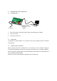
2. CONNECTION and LIMITATION 2.1. CONNECTION USB AC adopter Display Port (DP) / HDMI 1. Connect the PC by USB cable and the image cable (Display port / HDMI). 2. Turn on a monitor. 3. Launch the service tool. 2.2. LIMITATION To upgrade the scalar firmware, it is necessary to set the PC graphics board to its default color settings. 2.3. USAGE AT MULTI DISPLAY When using this tool with a notebook PC, it is necessary to set a resolution setting for LL-S201A to 1920x1080.
3. COMPOSITION OF THE SERVICE TOOL SCREEN 1. Button The action is executed. A message window comes out if needed. 2. Edit box It is a box for the character input from keyboard. Action is decided by pushing the button related to the box concerned after an input. 3. Check box Action is executed by choosing a box of item to check, and pushing the VersionUP button. 4. Radio button One is chosen from more than one candidate. Action is executed by choosing and pushing the ModelChange button.
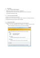
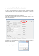
4. MAKE A CONNECTION BETWEEN LL-S201A AND PC In order to operate each function, it is necessary to change LL-S201A and PC into connection state. The start-up state of ServiceTool is “Not Connected”, so please push the “Connect” button first. When the cable is not connected, or when there is no response from a display, the message of the purport as “connection error” is displayed. If the cable is connected normally, and there is no response from a display, the main board may not be operating.
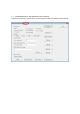
When PC connection is made normally, following information is displayed. 1. The current version number (Version UP) 2. The destination of model (MODEL) 3. Serial number (Serial Number) 4. Usage time of LED back light (Back Light Usage Time) ① ② ③ ④ Memo: The service mode of the touch display can also check the above information.
5. QUICK SUMMRY OF THE FEATURE 5.1. Firmware version up (Version UP) The controller software of LL-S201A is updated if necessary. 5.2. Setting the destination of model (MODEL) The destination setting is set or changed in case of board exchange and the repair. 5.3. Changing the serial number (Serial Number) The proper serial number of LL-S201A is written in case of the board exchange and the repair. 5.4.
6. FIRMWAER VERSION UP(Version UP) 6.1. Overview The LL-S201A is composed of the scaler part and the touch-panel part, and is upgraded by rewriting three firmwares. Upgrade of the scaler part rewrites software displaying a bit map image on a display. On the other hand, upgrade of the touch-panel part rewrites software via USB. Upgrade of two blocks can be set up individually. In addition, after the software of the touch panel is rewritten, it is necessary to insert power cycle.
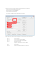
6.3. Scalor part version up 1 2 3 1. Change PC and LL-S201A into connection state. Version information is displayed when it is connected normally. 2. Select check box for Scaler. 3. Push the VersionUP button, the following message box will be displayed.
4. Push [OK] button, then version up will start. 5. During upgrade, the screen of LL-S201A becomes blackout. Moreover, LED becomes red mark light. 6. Upgrade takes about 1 minute. 7. When the upgrade succeeds, LL-S201A reboots and LED becomes green lighting. The following message box will be displayed on PC screen. 8. When an error occurs, the screen returns in about 15 seconds without rebooting. The following message box will be displayed on PC screen.
6.3.1. Notes during the upgrade 1. Don't Turn Off Power during upgrade. 2. Don't Take out the any cable. 3. Don't Touch the PC during upgrade. 4. Don't Place Another Window on Bit Map Data. Please keep in mind that writing is no longer performed normally and trouble may occur in a system action when the above operation is performed. USB AC adopter Display Port / HDMI Do not touch any things during upgrade Do not put any window on bitmap screen 6.3.2.
6.4. Touch part version up 1 2 3 1. Change PC and LL-S201A into connection state. Version information is displayed when it is connected normally. 2. Select check box for TC_Micon 3. Push the VersionUP button, the following message box will be displayed.
4. Push [OK] button, then version up will start. 5. A new window appears and upgrade will start automatically. Two kinds of software are rewritten. 6. Since the following message box is displayed when the upgrade succeeds, push the OK button after once AC/DC adaptor of display is pull out and reput and screen is displayed again. 6.4.1. Note during upgrade 1. Don't Turn Off Power during upgrade. 2. Don't Take out the any cable. 3. Don't Touch the PC during upgrade.
6.5. Simultaneous Upgrade (Scaler Part + Touch Part) At the time of selection of the check box -- [for Scaler] and [for TC_Micon] -- on upgrade, if both check box are chosen, scaler part + touch part are continuously upgradable. If upgrade of scaler part is completed, the following message box will be displayed, and if the [OK] button is pushed, upgrade of touch part will be started automatically. 6.6. NOTES AND LIMITATION 6.6.1.
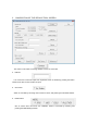
7. SETTING THE DESTINATION (MODEL) 7.1. Overview When the board is exchanged by board failure, it is necessary to set the destination. It can set up destination where there are three kinds, Japan, North America, Europe, and Europe2( Russia / Italy). 7.2. How to operate 1 3 2 Change PC and LL-S201A into connection state. 1. Choose the destination as JP(0) / US(1) / EU(2) / RUS, ITA(3). 2. Push the Model Change button. 3. When it succeeds, the following message box will be displayed.
8. SETTING THE SERIAL NUMBER(Serial Number) 8.1. Overview When the board is exchanged by board failure, it is necessary to take over the serial number of display. The serial number certainly should be the number indicated at the face plate on the back of display. 8.2. How to operate 1 2 3 1. Change PC and LL-S201A into connection state. The serial number currently recorded on the board will be displayed on the left side of a text box. 2. Input the serial number into the text box. 3.
9. SETTING USAGE TIME OF LED BACK LIGHT(Back Light Usage Time) 9.1. Overview It is used when taking over the back light usage time when the board is exchanged by board failure or resetting the usage time at the time of exchanging LCD module. Usage time can be specified per hour. Please keep in mind that it will be the requisite that usage time can read from the board.
10. WHITE BLANCE STTINGS BACKUP / RESTORE(White Balance Settings) 10.1. Overview The white balance setting is used to correct variations in each panel. When the panel is not changed, take over the panel setting to suppress variations. When the panel is changed, execute resetting to set the standard state. 10.2. How to operate (Backup / Restore) [In case of board change] 1. Change PC and LL-S201A into a connection state before board exchange. 2.
10.3. How to operate UI 3C01234Y-20130101.txt Taking into PC of the current White Balance preset value. 3C01234Y-20130101.txt Restore White Balance settings to new board.
Selecting the White Balance setting file. 10.4. Default setting file When LCD module is exchanged, please choose the default setting file and set data. The file is in the same position as the folder which installed the service tool. The file name is defaultWB.txt. 10.5. Note A White Balance setting file is automatically generated by the tool. Please keep in mind that a guarantee of operation is not offered when data is changed on a memo pad etc.
11. MISCELLANEOUS FEATURE 11.1. Factory reset(Factory Reset) 11.1.1. Overview Settings are returned to that of factory-shipment state. 1. Push the Factory Reset button. 2. Push [OK] button at confirmation dialog. 3. When setting initialization succeeds, the following message box will be displayed.
11.1.2. Detail of data Initialized (portion related to user ) Input port DisplayPort Volume 0 Mute disabled Child lock disabled Pen mode finger and pen OSD position normal Rotation normal Indicator displayed Splash Screen enabled Brightness 100 Contrast 75 Sharpness 4 Color temp. 6500K Hue 50 Saturation 50 Black level 50 R gain 100(RGB mode) G gain 100(RGB mode) B gain 100(RGB mode) Picture mode normal *Following settings are kept.
11.2. Aging (Aging) 11.2.1. Overview Displaying a self-pattern is continued in order to check whether a set carries out a normal performance. Red, blue, green, white and ashes, and a black pattern are repeated and displayed. 11.2.2. Start and stop 1. Push the Aging button. 2. Start Aging by clicking [OK] at the following message box. In order to quit the aging, please once pull out the AC/DC adaptor and put it again.
11.3. Power LED lighting test (Power LED Test) 11.3.1. Overview The lighting check of Power LED prepared in the lower right of LL-S201A. Displaying the pattern of green, red, orange, and putting out lights is repeated and continued. 11.3.2. Start and stop Push the PowerLED Test button. Push the OK button to stop.
11.4. Test pattern(Test Pattern) 11.4.1. Overview When LCD module is exchanged, to check a gap of a display position and the display of LCD module, a test pattern is displayed. 11.4.2. Start and stop Push the Test Pattern button, a test pattern will be indicated by the full screen. Push the [Esc] key of keyboard to end. Push the [Space] key of keyboard to flip the pattern.
Position gap of a panel is checked display of the LCD panel is checked [Space] key [Space] key Operation of line driver is checked
11.5. Touch Panel Controller Adjustment 11.5.1. Overview In this Model, the position gap correction value between LCD panel and touch panel is registered into touch panel control board. So, when a touch panel is replaced by new one, it is necessary to check the position gap between LCD panel and touch panel. And if the gap is over the acceptable value, adjustment work is needed. And drawing check is also required in order to confirm whether the new panel operates correctly. 11.5.2.
11.5.4. Setting-Limitation Setting: Before starting check and calibration - Connect PC and LL-S201A with USB and HDMI cable(or DP cable), - Set LL-201A to primary display or set multi display mode to duplicate or external only, if LL-S201A is connected as an external display. - If using touch position correction of Windows, reset the adjusted value before checking pen touch accuracy. Limitation: - In using touch pen, pen-writing with a hand on the screen is allowed.
11.5.5. Check Pen Touch Accuracy [PROCEDURE] (1) Start Check tool Click "TPC Adjustment" button on the tool for serviceman to start check tool. A gray cross and red and blue parallel lines are shown on the screen. Check whether touch position gap is settled in tolerance level according to the following procedure.
(2) With a touch pen, touch the center of the cross and check whether the touch position gap is settled in tolerance level. Because of the gap between pen tip and surface of LCD panel (glass and air gaps), a gap may arise between an actual touch position and a virtual position which is recognized as touch position by eyes. So, divide into gap of X-axis and Y-axis, and do check work. 1) Check the gap of X-axis component. Touch the center of gray cross with touch pen perpendicularly stood to the touch panel.
(3)End check tool Press "ESC" key to end the tool. (4)Confirm the result of Pen Touch Accuracy Check Click “ Yes” button, if passing the test of X and Y-axis gap. -> go to Drawing Check Click “No” button, if failing the test of X or Y-axis gap. -> go to Calibration Touch Position Click “Cancel” button, to quit TC Adjustment.
11.5.6. Calibration Touch Position Limitation: - Windows cannot recognize touch event during calibration. So, during calibration, use another pointing device such as mouse. - A keyboard is required, to press ESC key in calibration. [PROCEDURE] (1) Before starting calibration, check rotation function is not active. (2) Start Calibration Touch Position Tool Click "OK" button on the soft for serviceman to start the calibration tool.
(3) Click “Start” button to start calibration. A red cross is displayed at the upper-left corner of screen. (4) Touch the center of red cross on screen by pen for about 1 second, then the color of red cross is changed from red to green and next red cross is displayed. are displayed in all. Nine red crosses Push ESC key with keyboard to go back to the previous cross.
11.5.7. Drawing Check [PROCEDURE] (1) Start drawing check tool Templete is shown on the screen. (2)Trace template and draw lines. (in order from 1 to 10) ・Draw lines with a finger. (not pen) ・Draw lines to each end of 4 corners and 4 sides. ・Check the following item. - There is no abnormal wobble and winding of line. - There is no abnormal broken line. - It is possible to draw smooth lines on template lines. - It is possible to draw lines to ends at four sides.
[OK and NG Example] (3)Press "ESC" key to end the tool. (4) Click the “Yes” button if passing Drawing Check. (5) Click the “OK” button to finish.
(6) Click the “No” button if failing Drawing Check. The following message box is appeared. In this case, the touch panel is out of order. And it is needed to replace it by new one. Click the “OK” button to finish.
End of Page