SERVICE MANUAL CODE: 00ZMXM450/S1E LASER PRINTER MODEL MX-M350/M450 U MX-M350/M450 N CONTENTS [1] GENERAL. . . . . . . . . . . . . . . . . . . . . . . . . . . . . . . . . . . . . . . . . . . . 1-1 [2] CONFIGURATION . . . . . . . . . . . . . . . . . . . . . . . . . . . . . . . . . . . . . 2-1 [3] SPECIFICATIONS . . . . . . . . . . . . . . . . . . . . . . . . . . . . . . . . . . . . . 3-1 [4] CONSUMABLE PARTS . . . . . . . . . . . . . . . . . . . . . . . . . . . . . . . . .
CAUTION Cautions on laser 785 nm Wave length +10 nm −15 nm North America: 35 cpm model: (6.2 µs ± 6.2 ns)/7 mm 45 cpm model: (4.8 µs ± 4.8 ns)/7 mm Europe: 35 cpm model: (6.2 µs ± 6.2 ns)/7 mm 45 cpm model: (4.8 µs ± 4.8 ns)/7 mm Pulse times Output power 0.2 mW - 0.4 mW At the production line, the output power of the scanner unit is adjusted to 0.4 MILLIWATT PLUS 8 % and is maintained constant by the operation of the Automatic Power Control (APC).
CONTENTS [1] GENERAL [5] Different points of MX-M350N/350U series from AR-M355/M455 . . . . . . . . . . . . . . . . . . . . . . . . .1-1 1. 2. Interior . . . . . . . . . . . . . . . . . . . . . . . . . . . . . . . . . . . . 5-2 2. Note for servicing . . . . . . . . . . . . . . . . . . . . . . . . . . . .1-1 3. Operation panel. . . . . . . . . . . . . . . . . . . . . . . . . . . . . 5-3 4. Job status screen (common to print, scan, fax and Internet fax) . . . . . . 5-4 5. BASE SCREEN. . . . . . .
[7] MAINTENANCE AND DETAILS OF EACH SECTION [9] SIMULATION [Maintenance System Table] . . . . . . . . . . . . . . . . . . . . . . .7-1 1. Outline and purpose . . . . . . . . . . . . . . . . . . . . . . . . . 9-1 1. Engine section . . . . . . . . . . . . . . . . . . . . . . . . . . . . . .7-1 2. Code-type simulation. . . . . . . . . . . . . . . . . . . . . . . . . 9-1 2. Scanner / DSPF . . . . . . . . . . . . . . . . . . . . . . . . . . . . .7-2 A. Operating procedures and operations . . . . . .
[1] GENERAL 1. Different points of MX-M350N/350U series from AR-M355/M455 8) Do not print anything which is prohibited from printing by law. The following items are normally prohibited from printing by national law. Other items may be prohibited by local law. • Money • Stamps • Adopted new operation panel with 8.9 inch LCD • Bonds • Addition of a blue screw to DV unit. • Stocks • Added firmware version-up using USB device by Sim 49-1.
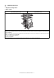
[2] CONFIGURATION 1. System configuration A.
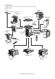
B. Option lineup For combinations of options, refer to "C. List of combination of peripheral devices" described later. (1) Major options 7. Finisher (AR-FN6) 10. Exit tray (AR-TE3 (The AR-DU4 is a standard provision. )) 11. Duplex module/bypass tray (AR-DU4) 1. Scanner module with DSPF (MX-EFX1) 8. Right upper exit tray (AR-TE5) 6. Upper exit tray (AR-TE4) 12. Duplex module (AR-DU3) 9. Mail-bin stacker (AR-MS1) 13. Saddle stitch finisher (AR-FN7) 2. Scanner rack (AR-RK2) 15.
No.
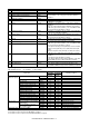
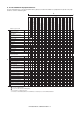
C. List of combination of peripheral devices As shown in the table below, some other peripheral devices (B) may be needed for installation of a peripheral device (A) and some peripheral devices cannot be installed together.
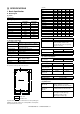
[3] SPECIFICATIONS (in mm) 1. Basic Specification A. Base Engine (1) Form Console type (2) Engine speed MX-M350U/ MX-M450U/ M350N M450N A4, 8.5" x 11" 35ppm (31ppm*) 45ppm (40ppm*) A4R, 8.5" x 11"R 25ppm 30ppm A5R/5.5" x 8.5"R, Invoice-R 35ppm 45ppm B5 35ppm 45ppm B5R, Executive-R 25ppm 30ppm B4/8.
B. Document Feeding Equipment (2) Support OS (1) One-drawer tray (included in the base engine) Custom PS Paper feed method Sizes to be fed Paper capacity Media available for paper feeding Paper type Custom PCL5e/6(XL) Paper size switching Dehumidification heater Balance detection Default size setting Mounting/demounting of the tray One-drawer tray A4, B5, 8.
b. Paper Input Function Paper size Paper type Custom paper type Source selection d.
Function Document filing PCL5e PCL6 PS Yes (MX-M350U/M450U: The MX-NBX3 is required.) PPD file *1 (for Windows XP) – c. Paper output Function Output tray selection *1: For printing, PS driver bundled with the Windows is required. (5) Macintosh driver functions a. General Function Copies Orientation Duplex Booklet N-up N-up order N-up border Macintosh PPD file (for Mac OS X ver10.2.
(6) Compatibility (5) Specified destination PCL5e PCL5e is compatible with HP LaserJet 4050. compatibility Small margin difference, rendering difference by different font family, default and transfer function difference is not to be included in the compatibility. PCL6 PCL6 is compatible with HP LaserJet 4050. compatibility Small margin difference, rendering difference by different font family, default and transfer function difference is not to be included in the compatibility.
(7) Functions Mode Transmit function Memory transmit On-hook Quick online transmit Manual transmit Auto reduction transmit Rotation transmit Scaling transmit Re-call mode Error Busy Book original transmit Long length original transmit Receive function Specified pages per file Maximum number of send data Sender name Address Confirmation Function (Prevention of missend) Auto receive Manual receive Memory receive Reduction receive for standard size Rotation receive Divided receive Scanner Internet Fax
C. Copy function (11) Registration-related settings Item Individual/ Group Program Memory box Scheduled send job Own number and Name Set User list (Reply-to List) Inbound Routing List Inbound routing addresses Sender Number/Address Registration (Inbound Routing) Subject (Send Settings) File name (Send Settings) Metadata Set List Rejected Number Rejected Address Polling permitted Number Registerable Number 999 (Up to 500 can be registered for 1 group.
3. B/W Scanner Module (DSPF) (7) Copy Function Function APS AMS XY zoom Paper type select Auto tray switching Rotation copy Electronic sort Rotation sort Special function Yes Yes Yes Yes (By type setting) Yes Yes Yes Yes (Europe, Australia, Agency) Reserved copy Yes (99 destinations) Recall/register of program Yes (10 destinations) Document filing Yes (MX-M350U/M450U: The MX-NBX3 is required.
OR guide display Rear left side (Print display) Left side OR guide (Print display) Interior side OR guide (Print display) Original reference position " " Supplied from the main unit (From the Interior side) 5-1/2, A5R, B5R, A4R/A5, 8.5", B4R/B5, 11", A3R/A4 (From the left side) 5-1/2, A5, B5, A4/A5R, 8-1/2, B5R, 11", A4R, 13", 14", B4R, A3R, 17" Interior side OR Book marks are at A4 and guide 8-1/2 positions.
[4] CONSUMABLE PARTS 1. Supply system table A. USA/Canada No. Item 1 Toner cartridge (Black) 2 Developer (Black) 3 Drum Content Toner cartridge (with IC) (Toner : Net weight 750 g) Developer (Developer : Net weight 500 g) OPC drum x 10 x 10 x1 Life 350K (35K x 10) 1000K (100K x 10) 200K Model name AR-455MT Remarks *Life setup is based on A4 6% AR-455MD AR-455DR B. European Subsidiary/East Europe/Russia/Australia/New Zealand No.
2. Maintenance parts list A. USA/Canada No.
C. Agency/Asia/Middle East/Africa/Latin America No.
E. China No.
2. Production number identification C. Developer cartridge The lot number is of 8 digit, and each digit indicates as follows. The lot number, printed on the front side flange, is composed of 10 digits, each digit showing the following content: 1 1 2 3 4 5/6 7 8/9 10 2 3 4 5 6 7 8 9 10 Number For this model, this digit is 2. Alphabet Indicates the model conformity code. T for this model. Number Indicates the end digit of the production year. Number or X, Y, Z Indicates the production month.
[5] EXTERNAL VIEWS AND INTERNAL STRUCTURES 1. Exterior 1 2 3 4 5 6 7 8 9 10 12 11 No. 1 Name 2 Exit tray 3 Automatic document feeder 4 Duplex module Function/Operation This tray can also be used for special papers including transparency film. The tray is extendable to support large size paper. Extend the tray when 11" x 17", 8-1/2" x 14", 8-1/2" x 13", A3 or B4 paper is being used. This automatically feeds and scans multiple sheet originals.
2. Interior 1 2 3 4 5 No. 1 2 3 6 Name Duplex module side cover Side cover latch Fusing unit Function/Operation Open when a misfeed has occurred in the duplex module. Push up to open the side cover when a misfeed has occurred in the main unit. Lift up to open the side cover when a misfeed has occurred in the main unit. 4 5 Toner cartridge (drum/toner cartridge) Photoconductive drum CAUTION: The fusing unit is hot. Take care in removing misfed paper.
3. Operation panel PRINT 1 2 When the document filing function has not been added. 3 PRINT READY DATA DOCUMENT FILING LINE DATA IMAGE SEND COPY SYSTEM JOB STATUS SETTINGS 4 No. 1 2 Name Touch panel 5 LOGOUT 6 7 8 9 10 11 Function/Operation The machine status, messages and touch keys are displayed on the panel. The document filing*1, copy, network scanner*2, fax*3, and Internet fax*4 functions are used by switching to the screen for the desired function.
4. Job status screen (common to print, scan, fax and Internet fax) This screen is displayed when the [JOB STATUS] key on the operation panel is pressed. This screen can be used to display the "JOB QUEUE" (showing stored jobs and the current job) or the "COMPLETE" job list (showing finished jobs). This screen can be used to check jobs, interrupt a job in progress to perform another job, and cancel a job.
5. BASE SCREEN To display the base screen of a mode, touch the [IMAGE SEND] key in the touch panel and then select the desired mode with the [MODE SWITCH] key. If you have set the display to show the address book screen when the [IMAGE SEND] key is pressed, touch the [CONDITION SETTINGS] key in the address book to display the condition setting screen.
B. Address book screen If you have set the initial screen to the address book screen using the Administrator setting, the initial screen will appear as follows. Destinations stored using the Web page are grouped in indexes (9) according to the letter entered in "Initial" for each destination, and the name entered in "Display Name" is displayed in the one-touch key (4). The screen shown below is the address book screen with an alphabetical index.
6. Cross sectional view A. Scanner unit 17 SPOD 16 1 2 3 SPPD 4 SPED 6 5 7 15 14 No. 1 2 3 4 5 6 7 8 9 13 12 11 10 Name CIS unit Original resist roller Original resist front sensor (SPPD) Original set sensor (SPED) Original take-up sensor Original length sensor 1 (SPLS1) Original length sensor 2 (SPLS2) CCD/lens unit Original feed roller 8 9 No. 10 11 12 13 14 15 16 17 Name Copy lamp base unit No. 1 mirror Copy lamp (Xenon) Mirror base unit No. 3 mirror No.
7. Switch, Sensor A.
8. PWB A. Scanner unit 2 1 3 13 6 4 5 12 11 8 10 9 No. 1 2 3 4 5 6 7 8 9 10 11 12 13 14 7 14 Name SPF control PWB Original size detection PWB (Light emitting side) CCD PWB (in lens unit) (The lens unit cannot be disassembled.) SPF original width detection volume PWB MFP operation PWB Scanner control PWB LVDS PWB Original size sensor (Light receiving side) CIS unit (in CIS unit) (The CIS unit cannot be disassembled.) CIS interface PWB (in CIS unit) (The CIS unit cannot be disassembled.
9. Motor, Clutch, Solenoid A. Scanner unit 5 3 1 4 2 7 6 No.
[6] UNPACKING AND INSTALLATION 1. Installing procedure flowchart There are many combinations between this machine and option units. For installing option units, observe the following procedures for efficiency. To install the devices effciently, follow the procedure below. Some peripheral devices may have been installed as standard devices depending on the main unit model. Part of descriptions and illustrations may be different.
2. Note for installation place Improper installation may damage this product. Please note the following during initial installation and whenever the machine is moved. 1) The machine should be installed near an accessible power outlet for easy connection. 2) Be sure to connect the power cord only to a power outlet that meets the specified voltage and current requirements. Also make certain the outlet is properly grounded. • For the power supply requirements, see the name plate of the main unit.
4. Unpacking and installation of the desk unit Caution: The lower tray cannot be pulled out unless the adjuster is lowered to the specified position. Note: In advance to installation of the machine, the paper feed option units (AR-D27/AR-D28/AR-MU2) should have been installed. <1> Pull out the paper tray of the main unit until it stops and then remove it by lifting both ends of the tray. 3) Put the main unit of the printer on the stand/paper drawer. A.
<2> Pull out the upper paper tray of the stand/paper drawer until it stops and attach the front mounting plates using a supplied screw for each. Then, remove the lock of the paper tray and close the tray. Remove the M4 screw shown in the illustration, insert the circle terminal of ground harness, and it fixes again. Front mounting plate Screw Front mounting plate Screw <3> Reattach the paper tray of the main unit.
B. AR-D27 • Start installation after checking that the DATA and COMMUNICATION indicators on the operation panel are neither lit nor blinking. <2> Hold the main unit of the printer at the positions shown in the illustration and put the main unit on the stand/paper drawer so that the front side and the left side of the main unit are aligned to those of the stand/paper drawer.
<3> Reattach the paper tray of the main unit. <3> Reattach the harness cover to its original position and fix it with the removed screw. At this time, ensure that the power supply I/F harness is arranged as shown in the illustration. • Fix the harness securely to the wire saddle. Screw Power supply I/F harness 5) Connect the power supply I/F harness to the PCU PWB of the main unit of the printer.
2) Put the main unit of the printer on the multi purpose drawer. <1> Pull out the paper tray of the main unit until it stops and then remove it by lifting both ends of the tray. <2> Pull out the paper tray of the multi purpose drawer until it stops and attach the front mounting plates using a supplied screw for each. Then, remove the lock of the paper tray and close the tray.
<3> Remove the filament tape that secure the the power supply I/ F harness. <3> Connect the connector (white, 4pin) of power supply I/F harness to the I/F connector (white, 4pin) of the main unit. Connect the power supply I/F harness connector (red, 22pin) to CN11 (red connector) of the PCU PWB of the main unit of the printer. Remove the M4 screw shown in the illustration, insert the circle terminal of ground harness, and it fixes again.
5. Unpacking and installation of the rack (AR-RK2) 6. Machine installing procedure A. Setting related to process 1) Open the left door and the front door, and remove the blue screw in the developer cartridge section. 2) Remove the developer cartridge from the machine. 1) Attach the rack to the desk unit. ★ Be sure to identify the left and the right racks. Refer to the figure below.
4) While rotating the MG roller, supply developer into the developer cartridge evenly. 3) Gently remove the sealing tape from the cartridge. Note that the MG roller must be rotated in the arrow direction as shown in the figure below. Use of a metal scale or a screwdriver (-) facilitates the procedure. Note: Before opening the developer seal, shake it 4 or 5 times. 4) Return the cartridge lock lever. 5) Attach the top cover to the developer cartridge and install the cartridge to the machine.
2) While pressing the paper holding plate, remove the fixing pin. 1) Turn off the main switch of the main unit of the printer. Turn the main switch located on the front side of the printer to the "OFF" position. Then remove the power plug from the outlet. "OFF" 2) Put the scanner unit on the rack. 3) Put paper in the tray, and close the paper feed tray. Hold the handle of the scanner unit, and put the scanner unit on the rack from the front side of the rack as shown in the figure.
5) Connect the cable. Connect the scanner unit connector with the printer connector, and fix the connectors with two screws attached to the connector. 6) Press the [START] key, and the automatic developer adjustment will be performed. During execution of the automatic developer adjustment, “EXECUTING...” is displayed and the toner sensor value is indicated on the LCD. (DEVE REFERENCE) 7) After about 2 min, the adjustment value is stored in the machine. Check that the mode was normally completed.
13. Using the transport handle [Fig. 2] 1) Remove the screw, and remove the handle. First copy image Image Paper Difference • Case of Fig. 2 Shift the cam A in the direction of B by the difference of the image. For one scale (one groove), shift by 0.5mm. After shifting the cam, tighten the cam A fixing screw (M3 x 12). Make a copy again and check to confirm that there is no distortion on the image. After adjustment, tighten the fixing screw (M3 x 12) and the scanner fixing screw (M4 x 8).
[7] MAINTENANCE AND DETAILS OF EACH SECTION • Self print of set values Use of SIM 22-6 allows to print the set values and the jam history of the machine. These values must be printed before execution of maintenance or disassembly procedures. • When assembling, check that the flat cable and the harness connectors are securely connected. • When connecting the flat cable, be careful not to break the pins.
2. Scanner / DSPF Maintenance cycle : 200K ✕ Check (Clean, replace, or adjust as necessary.
3. Peripheral devices Maintenance cycle : 50K ✕ Check (Clean, replace, or adjust as necessary.
[DETAILS OF EACH SECTION] 1. Process section A. General Toner is attached to electrostatic latent images formed by the laser beams which were radiated to the OPC drum charged by the main charger, forming toner images. The toner images formed on the OPC drum are transferred to paper by the transfer roller. 4 3 No. 1 2 3 4 5 Name Toner cartridge Developer unit Transfer roller Process drum unit Main charger unit 5 2 1 Operation Supplies toner to the developing unit, and collects waste toner.
Process Section Composition and Applying Voltage MAX 8KV constant current opc27 m ctc27 m 13 Separation electrode 3 12 1 -1.
[OPC drum section] A. General In this section the laser beam expose's the drum. The latent image is formed on the OPC drum. Then is sent to the development unit. B. Major parts and signal functions 8FE-BT-VK-N DSW-L 8 DSW-L 7 GND2 6 GND2 5 DM\ 4 DM-T 3 DMCLK\ 2 (NC) 1 DM PSPS PHNR-02-H+BU02P-TR-P-H 2 PSPS\ 1 1 +24V1 2 9 4 5 7 6 8 3 2 2 1 SRA-21T-4L RD SRA-21T-3 WH SRA-21T-4L WH SRA-21T-3 RD BIAS Code DM PSPS No.
C. Operational descriptions The OPC drum surface is negatively charged by the main charger. The laser beam images are radiated to the OPC drum surface by the laser unit to form latent electrostatic images. 3) After transfer operation, remaining toner is removed by the cleaning blade. 1) The OPC drum surface is negatively charged by the main charger. Main corona unit Drum High voltage unit Screen grid CTL CGL Aluminum layer OPC drum The main charger grid is provided with the screen grid.
D. Maintenance and parts replacement (1) Maintenance list Unit name Drum peripheral No. Part name 1 2 3 Drum DSD collar Cleaner blade 4 5 Toner reception seal Side molt F 6 Side molt R 7 8 Drum separation pawl unit MC unit When 100K 200K 300K 400K 500K 600K 700K 800K Remark calling ✕ ▲ ✕ ▲ ✕ ▲ ✕ ▲ ❍ ❍ ❍ ❍ ❍ ❍ ❍ ❍ ✕ ▲ ✕ ▲ ✕ ▲ ✕ ▲ Replace at 200K or 1 year. P/G No.: [10]-49 ✕ ▲ ✕ ▲ ✕ ▲ ✕ ▲ P/G No.: [10]-42 ✕ ▲ ✕ ▲ ✕ ▲ ✕ ▲ Apply side seal powder. P/G No.
a-1. MC unit 1) Remove the drum cartridge. 2) Check to confirm that the cleaning unit is inserted fully to the bottom. ∗ When installing, install the DSD collar R to the drum frame, then install the drum and the DSD collar F. When installing the DSD collar, engage the DSD collar boss with the drum frame hole. 3) Remove the pawl, and remove the MC unit. a-4. Drum separation pawl unit 1) Remove the drum cartridge. 2) Remove the screw, and remove the drum separation pawl unit.
a-6. Cleaner blade 1) Remove the drum cartridge. 2) Remove the drum and the DSD collar. 3) Pull it out until the cleaning unit stops. 4) Remove the screw, and remove the cleaner blade. ∗ When removing the drum blade, place the drum as shown in the figure and remove the drum blade to prevent toner from dispersing. ∗ Do not damage the cleaner blade. Do not touch the lead edge. ∗ When attaching the side molts F/R, attach them to the attachment reference as shown.
2) Remove the connector and the screw, and remove the PCU PWB unit. 3) Remove the screw and the connector, and remove the separation solenoid unit. 4) Remove the E-ring and the screw, and remove the separation solenoid. [Transfer section] A. General In this section, toner images on the OPC drum are transferred to paper. B.
8FE-BT-VK-N DSW-L 8 DSW-L 7 GND2 6 GND2 5 DM\ 4 DM-T 3 DMCLK\ 2 (NC) 1 DM 5 4 3 5 6 2 4 1 SRA-21T-4L RD SRA-21T-3 WH SRA-21T-4L WH SRA-21T-3 RD BIAS Code DM THV DHV No.
C. Operational descriptions 1) Toner image transfer Toner images formed on the drum by the developing roller are transferred to paper by the transfer roller. Toner on the drum is negatively charged by stirring in the developing unit. By applying a positive voltage to the transfer roller, the transfer roller and paper on the transfer roller are positively charged to transfer negatively charged toner images to paper. Separation electrode -1.
D. Maintenance and parts replacement (1) Maintenance list Unit name Transfer No. 1 2 3 4 5 6 Part name Transfer roller Discharge plate TR bearing (F/R) Transfer roller collar After-transfer star ring TR gear When calling ✕ ✕ ✕ 100K 200K 300K 400K 500K 600K 700K 800K Remark ✕ ✕ ✕ ✕ ✕ ✕ ▲ ▲ ✕ ✕ ✕ ▲ ✕ ✕ ✕ ✕ ✕ ✕ ▲ ▲ ▲ ▲ ✕ ▲ ✕ ✕ ✕ ✕ ✕ ✕ ▲ ▲ ✕ ✕ ✕ ▲ ✕ ✕ ✕ ✕ ✕ ✕ ▲ ▲ ▲ ▲ ✕ ▲ P/G No.: [5]-8 P/G No.: [5]-2 P/G No.: [5]-9, 18 P/G No.: [5]-10 P/G No.: [5]-19 P/G No.
a-2. Discharge plate 1) Remove the transfer roller unit. 2) Remove the screw, and remove the discharge plate holder and the discharge plate. a-3. Transfer roller a-4. Transfer roller collar a-5. TR bearing (F/R) a-6. TR gear 1) Remove the transfer roller unit. 2) Remove the screw, and remove the discharge plate holder and the discharge plate.
[Developing section] A. General In this section, toner is attached to electrostatic latent images formed by laser beams on the OPC drum, making visible images. B.
C. Operational descriptions Electrostatic latent images formed on the OPC drum by the Laser unit (LD image light) are converted into visible images by toner. layer Aluminum CGL CTL Drum -500V (-470V) Toner in the developing unit is stirred by the mixing roller. When toner is stirred, it is negatively charged by mechanical friction. The developing bias voltage (negative) is applied to the developing roller.
D. Maintenance and parts replacement (1) Maintenance list Unit name No. Developing section 1 2 3 4 5 Part name Developer DV blade DV side seal F DV side seal R Toner cartridge When 100K 200K 300K 400K 500K 600K 700K 800K Remark calling ▲ ▲ ▲ ▲ ▲ ▲ ▲ ▲ Supplied when installing ✕ ▲ ✕ ▲ ✕ ▲ ✕ ▲ P/G No.: [11]-55 ✕ ▲ ✕ ▲ ✕ ▲ ✕ ▲ P/G No.: [11]-38 ✕ ▲ ✕ ▲ ✕ ▲ ✕ ▲ P/G No.: [11]-43 Attached when installing./ 750g, user replacement for every 35K. 5 4 2 1 3 (2) Maintenance and parts replacement No.
a-1. Developer 1) Remove the DV cartridge. ∗ When attaching the DV blade, attach to the attachment reference shown in the figure below. 2) Remove the screw, and remove the DV cover. 0mm Reference (Step) 0.5mm 0mm 0.5mm Reference a-3. DV side seal F a-4. DV side seal R 1) Remove the DV cartridge. 2) Remove the DV side seal F and the DV side seal R. 3) Remove old developer. ∗ Use a metal scale or a minus screwdriver for easy operation. 4) Supply new developer.
a-5. Toner density sensor a-8. Toner motor a-6. Humidity sensor 1) Remove the toner cartridge. 1) Remove the DV cartridge. 2) Remove the screw, and remove the rear cabinet. 2) Remove the bottom cover. 3) Remove the bottom cover. 4) Remove the screw and the connector, and remove the humidity sensor. 2) Remove the connector and the screw, and remove the PCU PWB unit. a-7. Toner cartridge 1) Open the left door and the front door. 2) Release the lock and remove the toner cartridge.
2. Fusing section A. General This section explains how the toner is fused to the paper by heat and pressure. Paper exit Copy Fusing Fusing roller (Heating) Paper exit roller Main motor Fusing roller (Pressing) Heater lamps (2 pcs.) Power/ Filter PWB B.
Code RTH1 RTH2 HLTS HL1 HL2 MM Active Signal Name Type Function/Operation name condition RTH1 Fusing temperature Thermistor Detects the surface temperature of the fusing roller Analog input sensor (1) (heating). (Center section) RTH2 Fusing temperature Thermistor Detects the surface temperature of the fusing roller Analog input sensor (2) (heating). (Side roller section) HLTS Thermostat (1) Opens the circuit to the heater lamp when the temperature rises abnormally.
(5) Cleaning roller The fusing heat roller (heating) is provided with two heater lamps, which heat the fusing roller to fuse toner onto paper. The fusing section cleaning roller of this machine is made of the blast process. 1) Change to the fusing unit uses a colder roller to clean unwanted toner from the pressure roller. 2) Due to coating and the temperature characteristics of the upper heat roller, toner is not attached to the upper heat roller but to the lower heat roller.
(2) Maintenance and parts replacement No. a Unit Fusing unit 1 2 3 4 5 6 7 8 9 10 a a-9 a-8 Parts Lower separation pawl Upper separation pawl Thermistor Lower heat roller CL roller CL roller bearing Heater lamp Upper heat roller Upper heat roller gear Thermostat 3) Pull the fusing lever, and remove the fusing unit. ❍ ❍ ✕ ✕ ✕ ✕ ✕ ✕ a-2 a-4 a-6 a-5 a-1. Lower separation pawl a-1 a-3 a-7 a-10 a-6 a-3 1) Remove the fusing unit. 2) Open the fusing rear lower PG, and remove the lower separation pawl.
a-3. Thermistor a-5. CL roller 1) Remove the fusing unit. a-6. CL roller bearing 2) Remove the screw, and remove the fusing drawer. Remove the connector. 1) Remove the fusing unit. 3) Remove the screw, and remove the thermistor. 2) Remove the lower heat roller. 3) Remove the CL roller, and remove the CL roller bearing. a-7. Heater lamp 1) Remove the fusing unit. a-4. Lower heat roller 2) Open the fusing unit. 1) Remove the fusing unit. 3) Remove the screw, and remove the heater lamp.
3. Paper feed section a-8. Upper heat roller a-9. Upper heat roller gear 1) Remove the fusing unit. 2) Open the fusing unit. 3) Remove the fusing rear upper PG. 4) Remove the heater lamp. 5) Remove the upper heat roller, the roller stopper. The upper heat roller gear, and the upper heat roller bearing. A. General This section picks up paper in the cassette and feed it to the transport roller section. The capacity of the paper feed tray is 550 sheets for 64g/m2 or 500 sheets for 80g/m2.
B.
1 2 3 Name Take-up roller Paper feed roller Separation roller 4 5 Paper upper limit sensor Paper sensor 6 Lift-up motor Function Picks up paper and transports it to the paper feed roller. Feed paper in the machine. Rotates simultaneously with the paper feed roller to prevent against overlapped feed. For the manual feed tray, the separation pad is used instead of the roller. Detects the top surface of paper and stops paper at the feed position. Detects paper presence.
(3) Paper detection method of each tray 1) Machine 1st tray Paper detection is performed by VR in linkage with both side guides. 2) Multi-purpose tray Paper detection is performed by VR in linkage with both side guides and the detector in linkage with the rear edge plate. Width detection pattern C A G E D B A B F D D B Paper size B5 A4 B5R A4R Foolscap B4 A3 LT EX-R LTR LGL WLT Vertical detection pattern 1 2 3 4 5 6 7 2 3 4 6 7 For the other than above, the paper size is considered as "Extra.
[Paper remaining quantity detection] (1) Paper remaining quantity detection Paper remaining quantity detection is common in each tray except for the manual feed tray. Remaining quantity is indicated in 3 steps plus paper empty (4 steps in total). (2) Detection method Paper remaining quantity is detected by the number of times of changing of the remaining quantity sensor from when the tray starts lifting up to when the upper limit sensor turns on.
D. Maintenance and parts replacement (1) Maintenance list Unit name Paper feed No. 1 2 3 4 section Part name Pick-up roller Paper feed roller Separation roller Torque limiter When calling ✕ ✕ ✕ ✕ 100K 200K 300K 400K 500K 600K 700K 800K ✕ ✕ ✕ ✕ ✕ ✕ ✕ ✕ ✕ ✕ ✕ ✕ ✕ ✕ ✕ ✕ ✕ ✕ ✕ ✕ ✕ ✕ ✕ ✕ ✕ ✕ ✕ ✕ ✕ ✕ ✕ ✕ Remark Note 1 Note 1 Note 1 Note 1 Note 1: Replacement reference: Use the counter value of each paper feed port as the replacement reference.
3) Disengage the pawl, and remove the pickup roller and the paper feed roller. a-7. Cassette detection PWB 1) Remove the screw, and remove the rear cabinet. 4) Disengage the pawl, and remove the separation roller and the torque limiter. 2) Remove the connector, and remove the cassette detection PWB. a-5. Paper feed cassette upper limit detection a-8. Lift-up motor a-6. Paper feed cassette paper empty detection 1) Remove the screw, and remove the rear cabinet. 1) Pull out No.
3) Remove the E-ring, the gear, and the spring. 4) Remove the screw, and remove the lift-up motor. 4. Transport section/Paper exit reverse section A. General In this paper transport section, paper fed from each paper feed port is transported to the resist roller section, where the lead edge of the paper is aligned with the lead edge of images on the OPC drum. Images are transferred onto paper in the transfer section, and the paper is discharged face-up or face-down through the fusing section.
B.
RRC Signal name RRC Resist roller clutch Resist roller ON/OFF control TRC TRC Paper transport roller clutch Paper transport roller ON/OFF control MM MM Main motor Drives the paper transport and resist roller Code No. 1 2 4 5 Name Name Transport roller 15 Resist roller (Drive) Paper exit and transport roller Paper exit roller Function/Operation Type Electromagnetic clutch Electromagnetic clutch DC brushless Paper pass motor Function Transports paper to the transport resist roller.
3. Paper transport in duplex printing (with AR-DU3/DU4 installed) (1) Switchback operation and paper exit to the left tray 1) Paper transported from the fusing section is sent to the paper exit section of the machine. 2) When the male bin stacker (AR-MS1) or the finisher (AR-FN5) is installed, the paper entry gate solenoid (FGS) selects the paper entry gate to discharge paper outside the machine.
D. Maintenance and parts replacement (1) Maintenance list Unit name No. Part name 1 2 3 4 5 Resist roller Transport rollers Transport paper guides Paper dust remover unit Paper transport detection Transport section/ Paper exit reverse section When calling ✕ ✕ ❍ ❍ 100K 200K 300K 400K 500K 600K 700K 800K Remark ❍ ❍ ❍ ❍ ❍ ❍ ❍ ▲ ❍ ❍ ❍ ❍ ❍ ❍ ❍ ▲ ❍ ❍ ❍ ❍ ❍ ❍ ❍ ▲ ❍ ❍ ❍ ❍ ❍ ❍ ❍ ▲ P/G No.: [14]-51 2 2 4 1 2 5 (2) Maintenance and parts replacement No.
a-1. Paper dust remover unit b-1. Resist roller 1) Open the front door. 1) Remove the paper dust cleaner unit. 2) Remove the resist roller unit. 3) Remove the parts, and remove the resist roller. 4) Remove the gear, the parallel pin, and the E-ring. 2) Remove the paper dust cleaner unit. b-2. Paper transport roller 1) Remove the paper dust cleaner unit. 2) Remove the resist roller unit. 3) Remove the parts, and remove the paper transport roller. b.
4) Remove the screw and the connector, and remove the paper transport detector. 3) Remove the connector, the screw, and the washer, and remove the suction fan motor. 5) Remove the screw and the earth wire, and remove the high voltage resistor PWB. 4) Remove the screw, and remove the high voltage resistor PWB. ∗ When installing the fan, check the left door indication arrow and note the fan direction. c. Left door unit c-3. Drawer PWB 1) Remove the screw, and remove the left door unit.
d. Paper exit reverse unit 6) Remove the screw, and remove the paper exit tray cabinet. 1) Pull out the left door. 7) Remove the screw, and remove the front right upper cabinet. 8) Remove the front door. 2) Remove the screw, and remove the rear cabinet. 9) Remove the E-ring and the parts. 10) Remove the screw and the connector, and remove the paper exit reverse unit. 3) Remove the screw, and remove the paper exit upper cabinet. 4) Remove the screw, and remove the left rear cabinet.
d-2. Paper exit motor 1) Remove the paper exit reverse unit. 4) Remove the connector, the exhaust heat fan, the paper exit detection 2, the paper exit full detection. 2) Remove the connector and the screw, and remove the paper exit motor. d-3. Left door open/close detection 1) Remove the paper exit reverse unit. 2) Remove the connector and the screw, and remove the left door open/close detection. ∗ When installing the fan, check the indication arrow and note the fan direction. d-7.
d-8. Paper exit roller 1) Remove the paper exit reverse unit. 2) Remove the screw, and remove the paper exit upper paper guide unit. 3) Remove the E-ring, and remove the paper exit roller. Remove the bearing, the gear, and the parallel pin.
5. Laser scanner section A. General Image data sent from the MFP (image process circuit) through the mother board and PCU are converted into laser beams to expose the drum surface. B. Major parts and signal functions 5 1 2 10 6 PM BD 3 PCU PWB MFP MOTHER CONTROL BOARD PWB PWB CN1 Code PM BD No.
No. 1 2 3 4 5 6 7 8 9 10 Name Laser control PWB Cylindrical lens Incidence reflection mirror No. 1 mirror fθ lens 1 fθ lens 2 BD PWB No. 2 mirror Plane lens Convergence lens for BD Function Controls laser beam flashing and the output value. Converges laser beams to focus. Assures the optical path for laser beams. Assures the optical path for laser beams. Deflects laser beams so that the laser scan speeds on the both ends of the drum and that at the center of the drum are the same.
4) Remove the screw, and remove the rear cabinet. 8) Remove the screw, and remove the main switch mounting plate. 9) Remove the power unit. 5) Remove the connector, the screw, and the angle. Remove the snap band. ∗ Do not disconnect the LSU side. 10) Remove the connector and the screw, and remove the duct holding cover. 6) Pull out the No. 1 paper feed tray unit, and push up and remove the front door. 7) Release the lock, and pull out the left door. Remove the screw, and remove the front cover right.
6. Scanner section A. General There are following three methods of scanning documents in this machine. a. Place a document on the table glass. The copy lamp unit is operated to radiate copy lamp light onto the document, scanning the document with the CCD. b. The SPF feeds a document. The lamp illuminates the document and the image is scanned into the CCD that converts it from A/D. c. The SPF feed a document. The LED's of the CIS unit (attached to the SPF) aluminates the back side of the document.
B. Major parts and signal functions 11 MIM 6 1 2 CCD PWB 3 4 CL1 5 MHPS 10 CN1 IL-FPR-40S-VF-E1500 40 GND2 39 GND2 38 GND2 37 GND2 36 1_DATA1+ 35 1_DATA134 GND2 33 1_DATA0+ 32 1_DATA031 GND2 30 1_CLK+ 29 1_CLK28 GND2 27 /1_DBL+ 26 /1_DBL25 GND2 24 FRM_CCD1 23 PAGE1 22 CLK_CCD1 21 ADD_CCD1 20 TXD_CCD1 19 RXD_CCD1 18 RES_CCD1 17 GND2 16 +3.3V3 15 +3.
No. 1 2 3 4 5 6 Name Copy lamp unit Reflector No. 1 mirror No. 2 mirror No. 3 mirror CCD/Lens unit 7 White balance sheet 8 Table glass 9 SPF scan glass 10 Mirror home position sensor (MHPS) Scan motor DSPF white balance sheet 11 12 Function Lights up to radiate documents. A xenon lamp (operating on 3.15KV) is employed. This mirror converges lights on documents. Secures the optical path between a document and No. 2 mirror. Secures the optical path between No. 1 mirror and No. 3 mirror.
(3) Image signal flow (4) Carriage (lamp unit) shift (scan) speed The image signal converted into electric energy (analog signal) is A-D converted on the CCD PWB. Image processes such as white balance and shading correction are performed on the scanner control PWB. The image signal is then sent through the mother board to the MFP control PWB. The carriage scan speed depends on the copy magnification ratio.
D. Maintenance and parts replacement (1) Maintenance list Unit name Scanner section Part name Mirror/Lens/Reflector/Sensors Table glass/Dust-proof glass/OC White reference glass Rails Drive belt/Drive wire/Pulley When 100K 200K 300K 400K 500K 600K 700K 800K calling ❍ ❍ ❍ ❍ ❍ ❍ ❍ ❍ ❍ ❍ ❍ ❍ ❍ ❍ ❍ ❍ ❍ ❍ ❍ ❍ ❍ ❍ ❍ ❍ ❍ ❍ ❍ ✩ ✩ ✩ ✩ ✩ ✩ ✩ ✩ ✕ ✕ ✕ ✕ ✕ ✕ ✕ ✕ Remark 1 2 5 2 5 4 1 1 3 4 (2) Maintenance and parts replacement No.
a. Scanner unit a-6. Rails a-1. OC 1) Remove the table glass. 1) Remove the OC cover. 2) Grease up the rails. 2) 1) 3) 1) 4) 3) a-7. Drive wire a-8. Pulley a-2. Dust-proof glass a-9. Drive belt a-3. Table glass 1) Remove the table glass. a-4. White reference glass 2) Check the drive wire, pulley and drive belt. 1) Remove the table glass holder and the white reference glass holder, and remove the table glass and the white reference glass. 4) 4) 6) 5) 3) 1) 1) 2) a-10.
2) Pull out the harness from the scanner control PWB. a-14. Scanner interface PWB 3) Remove the scan motor. 1) Remove the table glass. 2) Remove the PWB cover and the harness cover. 3) 2) 1) a-11. OC open sensor 3) Remove the scanner interface PWB. 1) Remove the rear cabinet. 2) Remove the OC open sensor. 2) 1) 3) a-12. Mirror home position sensor b. Lamp unit 1) Remove the rear cabinet. 1) Remove the table glass. 2) Remove the mirror home position sensor. 2) Remove the scan lamp unit.
b-1. Reflector b-4. Inverter PWB b-1. Mirror 1) Remove the table glass. 1) Remove the table glass. 2) Hold with your hand and remove the screw. Remove the connector and remove the inverter PWB. 2) Clean the reflector and the mirror. b-3. Lamp 1) Remove the table glass. 2) Slide the lamp unit base to the notch section. c. CCD lens PWB unit 1) Remove the table glass. 2) Remove the dark-box cover. 1) 1) 2) 1) 1) 1) 3) Flip the notch section Mylar and remove the screw.
4) Clean the CCD lens and the CCD. Note for CCD lens PWB unit installation <1> Adjust the CCD unit adjustment value listed in the table below with the scribed line on the lens base. CCD unit adjustment value (+) direction Reference line (-) direction 1 scale: 1.4mm 7. DSPF section CCD adjustment value 5.0~ 3.6~4.9 2.2~3.5 0.8~2.1 -0.6~0.7 -2.0~ -0.7 -3.4~ -2.1 -4.8~ -3.5 ~ -4.
B.
2 9 4 3 6 7 12 11 SCOV SPFM Signal name SCOV SPFM1 SPFC SPFC SRRC SPED SPPD SPFS STMP SPLS1 SPLS2 SPFVR SRRC SPED SPPD SPFS STMP SPLS1 SPLS2 SPFVR SOCD SPOD SOCD SPOD Code No. 1 8 Function/Operation SPF cover switch SPF paper feed motor, paper transport motor SPF paper feed clutch Type SPF cover open/close detection Drives the paper feed roller and the transport roller.
D. Maintenance and parts replacement (1) Maintenance list Unit name No. Part name 1 2 3 4 5 6 7 Pick-up roller Paper feed roller Separation mylar lower Separation pad PS roller Paper exit roller Sensors DSPF section When calling ❍ ❍ ❍ ❍ ❍ ❍ 100K 200K 300K 400K 500K 600K 700K 800K ❍ ❍ ❍ ❍ ❍ ❍ ❍ ❍ ❍ ❍ ❍ ❍ ❍ ❍ ❍ ❍ ❍ ❍ ❍ ❍ ❍ ❍ ❍ ❍ ❍ ❍ ❍ ❍ ❍ ❍ ❍ ❍ ❍ ❍ ❍ ❍ ❍ ❍ ❍ ❍ ❍ ❍ ❍ ❍ ❍ ❍ ❍ ❍ ❍ ❍ ❍ ❍ ❍ ❍ ❍ ❍ Remark Note 2 Note 2 Note 2 Note 2 Clean with air.
a. SPF unit 2) Remove the stopper solenoid. 1) Remove the rear cabinet of the scanner section. 2) Disconnect the connector. 3) Disconnect the grounding wire. 2) 1) 1) 5) 5) 3) 4) 1) a-2. SPF document resist front sensor 5) a-3. SPF paper feed cover sensor a-4. SPF document set sensor 3) 2) 1) Remove the upper transport unit cover. 7) 1) 2) Remove the sensors. 6) 1) 4) Slide the SPF unit to the bottom, then remove it. 3) 4) 3) 2) 4) 4) 3) 1) 4) 3) 2) a-5.
a-6. SPF original length sensor 1 (SPF original width detection volume installation) a-7. SPF original length sensor 2 <1> Extend the original guide to the maximum position. 1) Remove the OC cover. <2> Adjust so that the mark on the width detection pinion gear is fitted with the mark on the volume mounting plate. 2) 1) 1) 3) 4) 3) 2) Remove the original length sensor cover, and remove the sensor. 1) 2) 1) <3> Fix the mounting plate with the screw.
a-11. CIS unit a-13. SPF open sensor a-12. CIS control PWB 1) Remove the open sensor. 1) Remove the upper transport unit cover. 2) Remove the CIS unit. 1) 2) a-14. SPF original exit sensor 1) Remove the paper exit sensor. 1) 2) ∗ When the CIS unit is replaced, the CIS shading adjustment must be performed. (Refer to the descriptions of ADJUSTMENTS.) 3) Remove the harness, the cover, the earth wire, and remove the CIS control PWB. a-15. Paper exit roller 1) Remove the original paper feed unit.
a-16. SPF motor 5) Remove the SPF motor. 1) Remove the OC cover. 1) 2) Remove the SPF lower cover. 1) 1) 2) 3) 1) 1) 1) 1) 2) 3) 1) 4) a-17. Resist roller a-18. Resist roller clutch 1) Remove the SPF resist roller unit. 3) Remove the original paper feed unit. 2) 1) 2) 2) 2) 3) 2) 2) 2) 2) Remove the SPF resist roller and the SPF resist roller clutch. 2) 2) 4) Remove the SPF drive unit.
a-19. SPF original paper feed solenoid a-21. Separation mylar lower a-20. SPF original paper feed clutch a-22. Separation pad 1) Remove the SPF paper feed unit. 1) Remove the upper transport unit. 2) Remove the SPF paper guide. 2) Loosen the screw, and remove the separation pad unit. 1) 1) 2) 3) Remove the screw, and remove the separation plate and the front separation plate. 3) Remove the SPF pickup unit. 4) Remove the separation Mylar lower, and the separation pad.
B. Major parts and signal functions FG SRA-21T-3 ORSLED B3B-EH +5V1 GND2 OCSW TOUCH 1 2 3 OCSW LCD ORSPD 1 CCFL 2 3 CN2 52271-1379 DISP YD LP CP +3.
Signal name Code LCD TOUCH OCSW CCFL No. 1 2 Function/Operation LCD unit Touch panel ORSLED ORSPD Name Document size detection light emitting PWB Document size detection light receiving PWB OCSW SPF open/close detector CCFL LCD backlight Generates the document size detection signal. Document size detection trigger LCD backlight Name LVDS/INV PWB Operation control PWB Unit Original detection unit 1 2 b Operation panel unit 1 2 3 4 5 Note Display the each memu and the information.
2) Remove the scanner left cabinet. b-1. MFP operation PWB 1) Remove the earth terminal. 2) Remove the MFP operation PWB 2) 1) 1) 3) Remove the scanner right cabinet. b-1. LVDS PWB 1) Disconnect each cables. 2) Remove the LVDS PWB. 2) 1) 1) 4) Remove the operation panel lower cabinet. Note for installation ∗ Tighten the ground screw and ground connector as shown in the below illustration. Improper placement will cause problems. 1) 2) 1) 1) 5) Remove the harnesses.
b-3. LCD INV-J PWB b-5. Touch panel 1) Disconnect each cables. 1) Disconnect the flat cable. 2) Remove the LCD INV-J PWB. 2) Remove the earth wire. 3) Remove the LCD unit. b-4. LCD unit 1) Disconnect each cables. 2) Remove the LCD cover. 5) Remove the touch panel. 3) Remove the LCD unit.
9. Filter A. Maintenance and parts replacement (1) Maintenance list Unit name Filters No. 1 Part name When calling Ozone filter 100K 200K 300K 400K 500K 600K 700K 800K ▲ ▲ ▲ ▲ ▲ ▲ ▲ ▲ 1 (2) Maintenance and parts replacement No. a Unit Parts 1 Ozone filter ▲ a-1. Ozone filter 1) Remove the paper exit tray cabinet cover, and remove the ozone filter. MX-M350/M450 N/U MAINTENANCE AND DETAILS OF EACH SECTION 7 - 67 Remark P/G No.
10. Drive section A. Maintenance and parts replacement (1) Maintenance list Unit name No. Part name Drive section 1 Gears (Specified position) When calling ✕ 100K 200K 300K 400K 500K 600K 700K 800K ✩ ✩ ✩ ✩ ✩ ✩ ✩ ✩ 1 1 1 (2) Maintenance and parts replacement No. a b Unit Drive unit 1 2 3 4 1 2 Parts Gears Paper cassette paper feed clutch Paper transport clutch Resist roller clutch Drum motor Main motor a. Drive unit 1) Remove the screw, and remove the left door.
3) Remove the screw, and remove the slide rail. ∗ Remove the resist roller unit, and apply grease to the bottom section of the PS front roller section brake. PS front roller section Apply grease FLOIL G484 4) Remove the connector and the screw, and remove the main drive unit. a-2. Paper cassette paper feed clutch a-3. Paper transport clutch a-4. Resist roller clutch 1) Remove the main drive unit. 2) Remove the parts. a-1. Gears 1) Remove the main drive unit.
4) Remove the connector, the paper cassette paper feed clutch unit, the paper transport clutch unit, and the resist roller clutch unit. 11. Power section A. Maintenance and parts replacement No. a Unit Power unit b 1 2 3 1 2 3 4 Parts Reactor PWB (200V only) Filter PWB (Taiwan only) PowerPWB RelayPWB Main switch Cooling fan motor Fuse PWB High voltage PWB 5) Remove the parts. b-2 b-4 b-3 a-1 b-1 a-2 a-3 a a. Power unit b-1. Drum motor 1) Remove the main switch mounting plate. b-2.
4) Remove the connector, and remove the screw. a-1. Reactor PWB (200V only) / Filter PWB (Taiwan only) 1) Remove the power unit. 2) Remove the connector and the PWB supporter, and remove the filter PWB. (200V only) 5) Remove the screw, and remove the rear cabinet. (Taiwan only) 6) Remove the connector, the screw, and the angle. Remove the snap band. a-2. Power PWB 1) Remove the power unit. 2) Remove the connector, the screw, and the PWB supporter, and remove the power PWB. 7) Remove the power unit.
a-3. Relay PWB 3) Remove the screw, and remove the main switch mounting plate. 1) Remove the power unit. 2) Remove the connector and the bushing, and remove the filter PWB mounting plate. 4) Remove the connector, and remove the main switch. 3) Remove the connector and the PWB supporter, and remove the relay PWB. b-2. Cooling fan motor 1) Remove the power unit. 2) Remove the connector and the screw, and remove the duct holding cover. b-1. Main switch 1) Pull out the No.
b-3. Fuse PWB 1) Remove the screw, and remove the rear cabinet. 2) Remove the connector and the screw, and remove the inlet mounting plate. 3) Remove the connector and the screw, and remove the high voltage PWB. 12. PWB A. Maintenance and parts replacement No. a 3) Remove the connector and the screw, and remove the fuse PWB. Unit 1 2 3 4 Parts MFP controller PWB HDD (Option) PCU PWB Mother PWB a-1 a-3 a-2 a-4 b-4. High voltage PWB a-1. MFP controller PWB 1) Remove the rear cabinet.
3) Release the lock, and remove the MFP controller PWB unit. 2) Remove the connector, and remove the screw. 3) Pull out the HDD unit. 4) Remove the screw, and remove the HDD cover. 4) Remove the screw, and remove the MFP controller PWB. 5) Remove the screw, and remove the HDD angle. a-3. PCU PWB 1) Remove the screw, and remove the rear cabinet. a-2. HDD (Option) 1) Remove the screw, and remove the right cabinet.
2) Remove the connector and the screw, and remove the PCU PWB. 10) Remove the screw, and remove the mother PWB. ∗ When replacing the PCU PWB, replace the EEPROM on the PCU PWB which is to be replaced. 13. Fan motor A. Maintenance and parts replacement No. Unit a a-4. Mother PWB 1) Remove the fusing unit. 1 2 3 Parts Controller cooling fan motor 1 Controller cooling fan motor 2 Ozone exhaust fan motor 2) Remove the paper exit reverse unit. 3) Remove the front cover right. 4) Remove the HDD cover.
2) Remove the screw, and remove the rear cabinet. 10) Remove the snap band, the screw, and the connector, and remove the fan fixing plate. 11) Remove the screw, and remove the controller cooling fan motor 1. 3) Remove the screw, and remove the paper exit upper cabinet. 4) Remove the screw, and remove the left rear cabinet. ∗ When installing the fan, note the fan direction. 5) Remove the screw, and remove the front left upper cabinet.
[8] ADJUSTMENTS No. Section 1 Process section 2 Image check, adjustment A B C A B 3 Scanner section A B C D E F G H I 7) Check the developing doctor gap. If the clearance is within the specified range, fix the screw with screw lock.
9) Move the adjustment plate in the arrow direction and adjust. C. High voltage output adjustment (1) Developing bias output check and setup 1) Remove the rear cabinet to allow checking of the high voltage monitor output pin. 2) Execute the simulation of the target high voltage. (See the table below.) 3) Select the mode to be set with 10-key, and press START key. 4) Enter the set value with 10-key and press START key. The set value is outputted for 30 sec.
2. Image check, adjustment A. Adjustments on the engine side (1) Copy image check <1> LSU right angle adjustment 1) Place a test chart (UKOG-0089CSZZ) on the reference position of the OC, and make a copy. Items which must have been completed before this adjustment. 2) Place a test chart (made as shown below) face-down on the (D)SPF, set the document guide, and make a copy.
<2> Print off-center adjustment a b Items which must have been completed before this adjustment. • LSU right angle adjustment (If there is no distortion in self print, the adjustment is not required.) Print lead edge Items which must be executed after completion of this adjustment. • Each tray resist amount setting • Print lead edge adjustment Print distortion adjustment • Front/rear and left/right void amount setting Measuring Specification Set value point Self print θ = 90° ± 0.
Item 2 TRAY1 3 TRAY2 4 DESK 5 BPT 6 ADU Set range Tray 1 resist 0 - 99 adjustment value Tray 2 resist adjustment value Desk resist adjustment value Manual tray resist adjustment value ADU resist adjustment value Default MXMXM350U/ M450U/ M350N M450N 65 60 55 50 55 50 60 55 55 50 [Output pattern] A <5> Front/rear and left/right void amount setting Items which must have been completed before this adjustment. When the set value is increased, the warp amount of paper is increased.
SIMULATION 50-1 LEAD EDGE ADJUSTMENT. SELECT 0-9, AND PRESS START. 0.TRAY SELECT 1 1.COPY START 2.MAGNIFICATION 100 (ADJUSTMENT DATA) 3.RRCA 50 4.RRCB 50 10.SIDE2 ADJ. 50 (IMAGE LOSS SETTING) 5.LEAD 15 6.SIDE 20 (VOID SETTING) 7.LEAD_EDGE(DENA) 35 8.TRAIL_EDGE(DENB)35 9.
4) Execute SIM51-2 to check the SPF set value. a a Change the set value of the SPF resist amount to the following value. 7 8 SPF (HIGH) SPF (LOW) 60 75 SIMULATION 51-2 RESIST TIMING ADJUSTMENT. SELECT 0-8, AND PRESS START. 0.TRAY SELECT 1 1.PRINT START 2.TRAY1 60 3.TRAY2 50 4.DESK 50 5.BPT 55 6.ADU 50 7.SPF(HIGH) 60 8.SPF(LOW) 75 1 b 5) Though the SPF resist amount is the above value, if there is any distortion in SPF scan, adjust the SPF installing position in the following procedures.
SIMULATION 48-1 MAGNIFICATION ADJUSTMENT. SELECT 0-7, AND PRESS START. 0.TRAY SELECT 1 1.COPY START 2.MAGNIFICATION 100 3.CCD(MAIN) 50 4.CCD(SUB) 50 5.SPF(MAIN) 50 6.SPF(SUB) 50 7.CIS(MAIN) 50 SIMULATION 48-1 MAGNIFICATION ADJUSTMENT. SELECT 0-7, AND PRESS START. 0.TRAY SELECT 1 1.COPY START 2.MAGNIFICATION 100 3.CCD(MAIN) 50 4.CCD(SUB) 50 5.SPF(MAIN) 50 6.SPF(SUB) 50 7.CIS(MAIN) 50 2 2 Select other than 0 - 2, and press [START] key.
<6> OC scan lead edge adjustment Output result Items which must have been completed before this adjustment. Rear edge void Lead edge void Document set reference • Adjustment on the engine side (If there is no problem in self print, no need to adjust.) Adjust with RRCA. Adjust with RRCB. • OC scan distortion adjustment • SPF scan distortion adjustment Image loss (SIDE) FR void • OC scan magnification ratio adjustment Items which must be executed after completion of this adjustment.
Normal display ERROR display Door open Jam Paper empty NOW COPYING DOOR OPEN. JAM PAPER EMPTY. 1 2 3 4 5 • For the duplex mode (Single → Duplex), add 10 to the above set value. • When the print line is shifted toward a from the paper center, decrease the value. • When the print line is shifted toward b from the paper center, increase the value.
B. Vertical image distortion balance adjustment (Copy lamp unit installing position adjustment) D. Vertical (sub scanning direction) distortion adjustment [Winding pulley position adjustment] 1) Insert the front/rear mirror base drive wire into the frame groove and press and fix it with the wire holder. At that time, do not tighten the wire fixing screw. Change the direction of the lamp positioning plate.
4) Loosen the fixing screw of the front or the rear frame mirror base drive pulley. •If La < Lb, turn the rear frame mirror base drive pulley in direction B. (Do not move the mirror base drive pulley shaft.) •If La > Lb, turn the rear frame mirror base drive pulley in direction A. (Do not move the mirror base drive pulley shaft.) Rear side 5) After completion of adjustment, press the original detection light emitting unit fully downward with your finger and release it.
H. Image density adjustment (1) Copy mode The image density adjustment is required for the following copy quality mode by using the simulation. a. Test chart setting There are two methods; the collective adjustment and the individual adjustment of the copy quality mode. • Copy mode Copy quality mode Collective Binary value mode Auto mode Character mode Character/Photo mode Photo mode Adjustment Individual adjustment 1) Place a test chart (UKOG-0162FCZZ) on the original table as shown below.
<2> Individual adjustment of each copy quality mode SIMULATION 46-2 EXP. LEVEL SETUP (2). SELECT 0-6, AND PRESS START. 0. TRAY SELECT 1 1. COPY START 2. EXP LEVEL 1 3. AE 3.0 50 4. CH 3.0 50 5. MIX 3.0 50 6. PHOTO 3.0 50 1 Select other then 0 - 2, and press [START] key. Press [SYSTEM SETTINGS] key. SIMULATION 46-2 EXP. LEVEL SETUP (2). INPUT VALUE 0-99, AND PRESS START. 3. AE 3.0 50 Select 1, and press [START] key. Press [START] key.
(Fax mode image density adjustment items) Image mode Fax mode print density adjustment (standard mode) Fax mode print density adjustment (smallcharacter mode) Auto Binary mode mode Manual Binary mode Fax mode print density adjustment (fine mode) Auto mode Auto mode Manual Manual Fax mode print density adjustment (super fine mode) Auto mode Fax mode print density adjustment (600dpi mode) Auto mode Manual Manual Binary mode Half tone mode Binary mode Half tone mode Binary mode Half tone mode Bin
b. Adjust the fax mode print density (standard mode/ small-character mode/super fine mode/600dpi mode) Item This adjustment is intended to the print mode for each Fax mode individually. In manual mode, the print density setting for each print density adjustment level (1 to 5) can be adjusted to a custom density level. 1) Set the test chart (UKOG-0162FCZZ) on the original table so that it aligns with the front frame. Then put four or five pieces of A3 (11" x 17") paper .
Set Default range – – Item 0 1 2 3 4 5 6 7 8 9 10 TRAY SELECT PRINT START EXP LEVEL AUTO 1.0 2.0 3.0 4.0 5.0 AUTO (H) 1.0 (H) 11 2.0 (H) 12 3.0 (H) 13 4.0 (H) 14 5.
[9] SIMULATION 1. Outline and purpose The simulation has the following functions to grasp the machine operating status, identify the trouble position and causes in an earlier stage, and make various setups and adjustments speedily for improving the serviceability of the machine.
START (Copy mode) Press the Program key. Press the asterisk (*) key. Press the clear key. Press the asterisk (*) key. Press the SYSTEM SETTINGS key Standby for entry of SIM code. Enter the main code of SIM with the 10-key. The main code of SIM is displayed. NO Press the START button. YES Standby for entry of SIM sub code YES Is there a sub code ? Press the SYSTEM SETTINGS key NO Enter SIM sub code with the 10-key.
B. Simulation list Code Main Sub 10 1 (1) Main/ Sub Code Main Sub 1 1 2 2 1 2 3 3 2 3 6 10 20 21 4 2 3 5 1 2 3 6 1 2 7 8 1 6 8 1 2 6 17 9 1 2 Function (Purpose) Used to check the operations of the scanner (read) unit and its control circuit. Used to check the operation of sensor and detector in the scanning (read) section and the related circuit. Used to check the operations of the automatic document feeder unit and the control circuit.
Code Main Sub 24 3 4 5 6 7 9 10 11 15 25 1 2 26 3 5 6 10 18 30 35 38 41 50 52 68 27 1 5 Function (Purpose) Used to clear the number of use of the finisher, SPF, and the scan (reading) unit. Used to reset the maintenance counter. Used to reset the developer counter. (The developer counter of the DV unit which is installed is reset.) Used to reset the copy counter. Used to clear the OPC drum counter. (Perform this simulation when the OPC drum is replaced.
Code Main Sub 46 15 16 17 18 19 20 21 22 23 24 25 27 31 39 45 48 46 1 5 49 50 6 1 1 2 5 6 7 10 12 27 Function (Purpose) Used to adjust the print density in the FAX mode (each super fine mode). (Only when FAX is installed.) Used to adjust the print density in the FAX mode (each ultra fine mode). (Only when FAX is installed.) Used to set the gain in shading correction. Used to adjust the gamma (density gradient) in the copy mode.
Code Main Sub 65 1 2 66 1 2 3 4 5 6 7 8 9 10 11 12 13 14 15 Function (Purpose) Used to adjust the touch panel (LCD display section) detection position. Used to check the result of the touch panel (LCD display) detection position adjustment. (The coordinates are displayed.) Used to change and check the FAX soft switch functions. (Used to change and check the functions provided for the FAX soft switches.
C. Details 2 2-1 1 1-1 Purpose Function (Purpose) Section Item Operation test/Check Used to check the operations of the scanner (read) unit and its control circuit. Optical (Image scanning) Operation Operation/Procedure Purpose Function (Purpose) Section Item Operation/Procedure 1) Select the operation mode with 10-key. 2) Press START key. The SPF repeat paper feed, transport, and paper exit at the speed corresponding to the operation mode. 1) Select the operation mode with 10-key.
SIMULATION 2-2 SPF SENSOR CHECK. SPFSET SOCD SPPD SPOD SWD4 SWD3 SPLS2 SPLS1 SWD_LEN: 2100 SCOV SWD6 SWD2 CISSET SWD_AD: 600 SPED SWD5 SWD1 STSET 2-3 Purpose Function (Purpose) Section Item Operation test/Check Used to check the operations of the loads in the automatic document feeder unit and the control circuits. DSPF Operation Operation/Procedure 1) Select the number corresponding to the target of operation check with 10-key. 2) Press START key. The load selected in procedure 1 is operated.
(Built-in finisher) SIMULATION 3-3 FINISHER SENSOR CHECK. PID SCID SCPD POD T2DN T2PD STNC STHP PSHP STUHP STTHP2 DOPD 24VM MMLK SIMULATION 3-3 FINISHER LOAD TEST. SELECT 1SCID2 T1PF STSP JFHP STTHP1 DSW1 PPD T2UP STLS JRHP 2 Press [START] key, and the operation is started. Press [SYSTEM SETTINGS] key, and the operation is stopped. DSW2 SIMULATION 3-3 FINISHER LOAD TEST. EXECUTING (Console finisher) SIMULATION 3-2 FINISHER SENSOR CHECK.
Set Initial 1STEP range value 0 - 200 100 0.04374mm Item 5 Staple rear one-position binding position adjustment 6 Staple front one-position 0 - 200 binding position adjustment 7 Staple 2-position binding 0 - 200 center adjustment 8 Staple 2-position binding pitch 0 - 99 adjustment 9 Punch center adjustment 47 - 53 (Slide direction) 10 Punch hole position 0 - 99 adjustment (Paper feed direction) SIMULATION 3-10 CONSOLE FINISHER SETTING. 1.SADDLE POSITION 3.FRONT ADJUST 4.REAR ADJUST 6.STAPLE FRONT 8.
DDRS DSPD2 DSPD1 DCSS24 DCSS23 DCSS22 DCSS21 DLUD2 DPED2 DPFD3 DCSS14 DCSS13 DCSS12 DCSS11 DLUD1 DPED1 DPFD2 MCSS4 MCSS3 MCSS2 MCSS1 MCSPD MCLUD MCPED DPFD1 4-3 Desk door sensor Desk cassette 2 remaining paper quantity sensor Desk cassette 1 remaining paper quantity sensor Desk cassette 2 paper rear edge sensor 4 Desk cassette 2 paper rear edge sensor 3 Desk cassette 2 paper rear edge sensor 2 Desk cassette 2 paper rear edge sensor 1 Desk cassette 2 upper limit sensor Desk cassette 2 paper sensor De
5-3 5 5-1 Purpose Function (Purpose) Section Item Operation test/Check Used to check the operation of the display, LCD in the operation panel, and control circuit. Operation (Display/Operation key) Operation Operation/Procedure Purpose Function (Purpose) Section Item Operation test/Check Used to check the operation of the scanner lamp and the control circuit. Optical (Image scanning) Operation Operation/Procedure 1) Select the number corresponding to the target of operation check with 10-key.
18*1 19*2 20*2 21*2 MCLUM MPFS MPFC MSS MP tray lift-up motor signal Manual paper feed solenoid signal Manual paper feed clutch signal Manual paper feed gate solenoid 7 7-1 *1: Displayed when OPTION of multi-purpose only. *2: Displayed when manual feed OPTION is added. SIMULATION 6-1 FEED OUTPUT CHECK. SELECT 1-22, AND PRESS START. 1.MSWPR 2.HLPR 3.DCPR 4.MM 5.DM 6.DSB_FW 7.DSB_RV 8.CPFC 9.RRC 10.TRC 11.FGS_FIN 12.LUM 13.TRC_DSK 14.PSPS 15.MCM 16.MCPCL 17.MCFCL 18.MCLUM 19.MPFS 20. MPFC 21.MSS 22.
7-6 8 Purpose Function (Purpose) Section Item Setting Used to set the intermittent aging cycle. 8-1 Purpose Function (Purpose) Operation Operation/Procedure 1) Enter the intermittent aging cycle (unit: sec) with 10-key. 2) Press [START] key. The time entered in procedure 1) is set. Section Adjustment/Operation test/Check Used to check and adjust the operations of the developing voltage of each color and the control circuit.
4) Press [START] key. 8-2 Purpose Function (Purpose) Section Adjustment/Operation test/Check Used to check and adjust the operation of the main charger grid voltage in each printer mode and the control circuit. Image process (Photoconductor/Developing/ Transfer/Cleaning) (The set value is stored, and the voltage corresponding to the set value is outputted for 30sec.) Press [SYSTEM SETTINGS] key to stop the operation. (The transfer output voltage adjustment and output check can be made in each print mode.
9-2 SIMULATION 8-17 TRANSFER ROLLER SETTING. SELECT 1-3, AND PRESS START. 1.SHV FRONT 160 2.SHV BACK 160 3.THV- 780 1 Press [START] key. Press [SYSTEM SETTINGS] key. Purpose Function (Purpose) Section Item Operation test/Check Used to check the operations of the sensors and detectors in the duplex section and its control circuit. Duplex Operation Operation/Procedure SIMULATION 8-17 TRANSFER ROLLER SETTING. INPUT VALUE, AND PRESS START. 1.FRONT (0-240) 160 Press [START] key.
13 15 13-0 15-0 Purpose Function (Purpose) Section Item Clear/Cancel (Trouble etc.) Used to cancel the self-diag "U1" trouble. (Only when FAX is installed.) FAX Trouble Operation/Procedure Purpose Function (Purpose) Section Item Clear/Cancel (Trouble etc.) Used to cancel the self-diag "U6-01, 02, 03, F312, 22" (large capacity paper feed tray, paper feed trays 1, 2) troubles. LCC Trouble 1) Select 1 (YES) with 10-key. Operation/Procedure 2) Press [START] key. (The trouble display is canceled.
17 22 17-0 22-1 Purpose Function (Purpose) Section Item Clear/Cancel (Trouble etc.) Used to cancel the PF troubles (when the copy inhibit command from the host computer is received). Communication unit (TEL/LIU/MODEM etc.) Trouble Error Purpose Function (Purpose) Item Adjustment/Setup/Operation data output/Check (Display/Print) Used to check the print count value in each section and each operation mode. (Used to check the maintenance timing.
22-3 Purpose Function (Purpose) Section Item Adjustment/Setup/Operation data output/Check (Display/Print) Used to check misfeed positions and the misfeed count of each position. (If the misfeed count is considerably great, it may be judged as necessary to repair.) Sections other than SPF/DSPF section Trouble Misfeed Operation/Procedure The history of paper jams and misfeed is displayed. The misfeed history is displayed sequentially from the latest one. The max.
Code FPOD_N FPOD_S FES_N FES_S FFPS_N FFPS_S FSTPL FPNCH FDOP PID_N PID_S MPPD1_N MPPD1_S MPPD2_N MPPD2_S MPPD3_N MPPD3_S MPPD4_N MPPD4_S MPPD5_N MPPD5_S Description Built-in finisher POD not-reaching jam Built-in finisher POD remaining jam Console finisher entry port sensor (FES) not-reaching jam Console finisher entry port sensor (FES) remaining jam Console finisher saddle not-reaching jam (Not reaching the folding sensor (FFPS).
22-10 22-7 Purpose Function (Purpose) Item Adjustment/Setup/Operation data output/Check (Display/Print) Used to display the key operator code. (This simulation is used when the customer forgets the key operator code.) Data User data Operation/Procedure Purpose Function (Purpose) Item Adjustment/Setup/Operation data output/Check (Display/Print) Used to check the system configuration (option, internal hardware). Specifications Options Operation/Procedure The system configuration is displayed.
Item HDD NIC PS3 expansion kit FAX Network scanner Expansion memory Display 0MB ****MB ---MX-NBX2/ NBX3 ---AR-PK6 ---AR-FX12 ---MX-NSX1 ---AR-MM9 Handset Finish stamp ---AR-HN5 ---AR-SU1 Content Hard disk not installed Hard disk installed NIC not installed NIC installed PS3 expansion kit not installed PS3 expansion kit installed FAX expansion kit not installed FAX expansion kit installed Network expansion kit not installed Network expansion kit installed Expansion memory for FAX not installed Expansion
22-31 22-19 Purpose Function (Purpose) Section Item Adjustment/Setup/Operation data output/Check (Display/Print) Used to check the values of the counters related to the scan mode and the Internet FAX mode. Scanner Counter Operation/Procedure The values of the counters related to the scan mode and the Internet FAX mode are displayed.
4) Press [START] key. SIMULATION 24-1 JAM/ TROUBLE COUNTER DATA CLEAR. SELECT1-3, AND PRESS START. 1. PAPER JAM 2. SPF JAM 3. TROUBLE The list of the ON time of the sensors and the detectors of the paper transport section is printed. When a paper jam or misfeed is generated, the ON time of each sensor and detector is checked to check if the operation of the sensor and the detector, paper feed, and transport are normal or not.
24-3 Purpose Function (Purpose) Section Item SIMULATION 24-4 MAINTENANCE COUNTER DATA CLEAR. PRESS START. 1. MAINTENANCE Data clear Used to clear the number of use of the finisher, SPF, and the scan (reading) unit. 1 Counter Operation/Procedure Press [START] key. Press [SYSTEM SETTINGS] key or [START] key. 1) Select the counter to be cleared with 10-key. 2) Press [START] key. SIMULATION 24-4 * COUNTER DATA CLEAR. ARE YOU SURE? 1. YES 2. NO The confirmation to clear is opened.
1 COPY 3) Select Yes/NO of counter clear with 10-key. Copy effective paper counter YES: Clear SIMULATION 24-6 COPY COUNTER DATA CLEAR. PRESS START. 1. COPY NO: Not clear 4) Press [START] key. 1 After replacing the OPC drum, be sure to clear the OPC drum counter. 1 2 Press [START] key. PRINTER OTHERS Press [SYSTEM SETTINGS] key or [START] key. SIMULATION 24-6 * COUNTER DATA CLEAR. ARE YOU SURE? 1. YES 2. NO SIMULATION 24-9 PRINTER/OTHERS COUNTER DATA CLEAR. SELECT1-2, AND PRESS START. 1.
24-11 Purpose Function (Purpose) Section Item Data clear Used to reset the OPC drum rotation time, and the DV unit rotation time counter. The developer counter in the DV unit installed is reset. Image process (Photoconductor/Developing/ Transfer/Cleaning) Counter Developer Operation/Procedure 1) Select the counter to be cleared with 10-key. 2) Press [START] key. The confirmation to clear is opened. 3) Select Yes/NO of counter clear with 10-key. YES: Clear NO: Not clear 4) Press [START] key.
(Default: 1) 25-2 Purpose Function (Purpose) Section Setting Used to make the initial setting of toner concentration when replacing developer. Image process (Photoconductor/Developing/ Transfer/Cleaning) SIMULATION 26-3 AUDITOR SETUP. SELECT 1-3, AND PRESS START. 1.P10 2.VENDOR 3.OTHERS 4.VENDOR-EX 5.VENDOR-EX+ Operation/Procedure 1 1) Press [START] key.
9 10 AB_A CHINA AB series A5 China 0 1 Since this simulation cannot change the Fax destination, use SIM 66-2 to change the FAX destination. CE mark control NO (Normal operation) CE mark control YES (Heater lamp soft start operation) (Default: 1 for Europe, 0 for the others) SIMULATION 26-6 DESTINATION SETUP. SELECT 1-10, AND PRESS START. 1.USA 2.CANADA 3.INCH 4.JAPAN 5.AB_B 6.EUROPE 7.UK 8.AUSTRALIA 9.AB_A 10.CHINA SIMULATION 26-30 CE MARK CONTROL SETTING. SELECT 0-1, AND PRESS START. 0. NO 1.
• Effective paper counter 26-41 Purpose Setting Function Used to set the automatic magnification ratio (Purpose) selection (AMS) in the pamphlet mode. Section Item Specifications Operation mode (Common) Operation/Procedure 1) Enter the number corresponding to whether AMS operation is automatically performed or nor in the center binding mode with the 10-key. NO YES 1 26-68 Purpose Function (Purpose) Section Item 2) Press [START] key. 0 1 SIMULATION 26-52 BLANK PAPER COUNT UP SETTING.
27-5 Purpose Function (Purpose) Section Item Setting Used to enter the machine tag No. (This function allows to check the tag No. of the machine with the host computer.) Communication unit (TEL/LIU/MODEM etc.) Specifications Operation mode Operation/Procedure 1) Enter the tag number with 10-key. 2) Press [START] key. SIMULATION 27-5 TAG # SETTING. INPUT VALUE, AND PRESS START.
40-7 40-2 Purpose Function (Purpose) Section Item Adjustment Used to adjust the manual paper feed tray paper width detector detection level. Paper feed Operation Purpose Function (Purpose) Section Item Adjustment/Setup Used to enter the manual paper feed tray paper width adjustment value. Paper feed Operation Operation/Procedure Operation/Procedure 1) Open the manual paper feed guide to the max. width. 1) Select the number corresponding to the set item with 10-key.
41-2 40-12 Purpose Function (Purpose) Section Item Adjustment/Setup Used to adjust the multi-purpose tray width detection level. Paper feed Operation Purpose Function (Purpose) Section Item Adjustment Used to adjust the document size sensor sensing level. Other Operation Operation/Procedure Operation/Procedure 1) Open the paper feed tray 2 paper feed guide to the max. width position. 1) Open the document cover and select NO ORIGINAL with 10key without placing any document on the document table.
SIMULATION 41-3 PD SENSOR DATA DISPLAY. OCSW PD1[128]: 200 PD2[128]: 200 PD3[128]: 50 PD4[128]: 52 PD5[128]: 51 PD6[128]: 50 PD7[128]: 52 SIMULATION 44-1 PROCESS CORRECTION VALUE SETTING. INPUT VALUE 0-255 AND PRESS START. BIT0:Vg1, BIT1:Ld1, BIT2:Vg2, BIT3:Ld2 BIT4:Vb1, Vb2 BIT5:Vg3, Vb3, Ld3 BIT6:Vbr BIT7:Vg4, Vb4, Ld4 111 44-4 43 Purpose Function (Purpose) Section 43-1 Purpose Function (Purpose) Section Item Setting Used to set the fusing temperature in each operation mode.
DEV REF 44-9 Purpose Function (Purpose) Section Item Adjustment/Setup/Operation data output/Check (Display/Print) Used to check the data related to the image forming section correction (process correction) result (corrected main charger grid voltage, the developing bias voltage, and the laser power voltage in each print mode). (This simulation allows to check that correction is performed normally or not.
3) Enter the number corresponding to the paper feed tray to be used with 10-key. Purpose Function (Purpose) 4) Press [START] key. (The paper feed tray is selected.) 1 2 3 4 5 TRAY1 TRAY2 TRAY3 TRAY4 BPT TRAY1 TRAY2 TRAY3 TRAY4 Manual feed Item SIMULATION 46-2 EXP. LEVEL SETUP (2). SELECT 0-6, AND PRESS START. 0. TRAY SELECT 1 1. COPY START 2. EXP LEVEL 1 3. AE 3.0 50 4. CH 3.0 50 5. MIX 3.0 50 6. PHOTO 3.0 50 1 Press [SYSTEM SETTINGS] key. SIMULATION 46-2 EXP. LEVEL SETUP (2).
46-10 SIMULATION 46-9 EXP. LEVEL SETUP (CHAR.2). SELECT 0-11, AND PRESS START. 0. TRAY SELECT 1 1. COPY START 2. EXP LEVEL 1 3. 1.0 50 4. 1.5 50 5. 2.0 50 6. 2.5 50 7. 3.0 50 8. 3.5 50 9. 4.0 50 10. 4.5 50 11. 5.0 50 1 Purpose Function (Purpose) Item Select other than 0 - 2, and press [START] key. Adjustment Used to adjust the print density for each density level (display value) in the copy mode (binary Text/Photo mode). An optional print density can be set for each density level (display value).
46-11 SIMULATION 46-10 EXP. LEVEL SETUP (MIX.2). SELECT 0-11, AND PRESS START. 0. TRAY SELECT 1 1. COPY START 2. EXP LEVEL 1 3. 1.0 50 4. 1.5 50 5. 2.0 50 6. 2.5 50 7. 3.0 50 8. 3.5 50 9. 4.0 50 10. 4.5 50 11. 5.0 50 1 Purpose Function (Purpose) Item Select other than 0 - 2, and press [START] key. Adjustment Used to adjust the print density for each density level (display value) in the copy mode (binary Photo mode). An optional print density can be set for each density level (display value).
4) Press [P] key or [START] key. SIMULATION 46-11 EXP. LEVEL SETUP (PHOTO2). SELECT 0-11, AND PRESS START. 0. TRAY SELECT 1 1. COPY START 2. EXP LEVEL 1 3. 1.0 50 4. 1.5 50 5. 2.0 50 6. 2.5 50 7. 3.0 50 8. 3.5 50 9. 4.0 50 10. 4.5 50 11. 5.0 50 The adjustment value is set. When [START] key is pressed, printing is perfumed and the adjustment value is set simultaneously. 1 Check the density of printed image. Normal display ERROR display Select other than 0 - 2, and press [START] key.
46-13 Purpose Function (Purpose) Item Adjustment Used to adjust the print density in the FAX mode (each normal mode). (Only when FAX is installed.) Picture quality Operation/Procedure 1) Select the number corresponding to one of the following adjustment items with 10-key. ∗ Manual mode (Print density adjustment level) SIMULATION 46-13 EXP.LEVEL SETUP FAX(NORMAL). SELECT 0-8, AND PRESS START. 0.TRAY SELECT 1 1.PRINT START 2.EXP LEVEL 1 3.AUTO 50 4.1.0 50 5.2.0 50 6.3.0 50 7.4.0 50 8.5.
46-14 Purpose Function (Purpose) Item Adjustment Used to adjust the print density in the FAX mode (each fine mode). (Only when FAX is installed.) Picture quality Operation/Procedure 1) Select the number corresponding to one of the following adjustment items with 10-key. (Select one of 3 - 14.) ∗ Normal mode (Print density adjustment level) ∗ Normal mode (Print density adjustment level) (Half-tone mode) ∗ Auto mode (Half-tone mode) Select other than 0 - 2, and press [START] key.
46-15 Purpose Function (Purpose) Item Adjustment Used to adjust the print density in the FAX mode (each super fine mode). (Only when FAX is installed.) Picture quality Operation/Procedure 1) Select the number corresponding to one of the following adjustment items with 10-key. (Select one of 3 - 14.) ∗ Normal mode (Print density adjustment level) ∗ Normal mode (Print density adjustment level) (Half-tone mode) ∗ Auto mode ∗ Auto mode (Half-tone mode) 3) Enter the print density level with 10-key.
46-16 Purpose Function (Purpose) Item SIMULATION 46-16 EXP.LEVEL SETUP FAX(ULTRA FINE).SELECT 0-14,AND PRESS START. 0.TRAY SELECT 1 1.PRINT START 2.EXP LEVEL 1 3.AUTO 50 4.1.0 50 5.2.0 50 6.3.0 50 7.4.0 50 8.5.0 50 9.AUTO(H) 50 10.1.0(H) 50 11.2.0(H) 50 12.3.0(H) 50 13.4.0(H) 50 14.5.0(H) 50 Adjustment Used to adjust the print density in the FAX mode (each ultra fine mode). (Only when FAX is installed.
Exposure level SIMULATION 46-17 CCD/CIS SHADING GAIN DATA SETUP. SELECT 1-3, AND PRESS START. 1.CCD ODD 80 2.CCD EVEN 80 3.CIS 128 Press [START] key. Press [SYSTEM SETTINGS] key. SIMULATION 46-17 CCD SHADING GAIN DATA SETUP. INPUT VALUE 0-255,AND PRESS START. 1.CCD ODD 80 46-18 Purpose Function (Purpose) Item Adjustment Used to adjust the gamma (density gradient) in the copy mode.
4) Press [START] key. SIMULATION 46-18 GAMMA SETUP(COPIER). SELECT 0-18, AND PRESS START. 0.TRAY SELECT 1 1.PRINT START 2.EXP LEVEL 1 3.OC_AE 64 4.OC_CHARA 5.OC_MIX 64 6.OC_PHOTO 64 7.SPF1_AE 64 8.SPF1_CHARA 64 9.SPF1_MIX 64 10.SPF1_PHOTO 64 11.SPF2_AE 64 12.SPF2_CHARA 64 13.SPF2_MIX 64 14.SPF2_PHOTO 64 15.CIS_AE 64 16.CIS_CHARA 64 17.CIS_MIX 64 18.CIS_PHOTO 64 Select other than 0 - 2, and press [START] key.
46-20 Purpose Function (Purpose) Section Item Adjustment Used to adjust the copy density correction in the SPF copy mode for the document table copy mode. The adjustment is made so that the copy density becomes the same as that of the document table copy mode. SPF Picture quality Density SIMULATION 46-20 OC/SPF EXP. ADJUSTMENT. SELECT 0-5, AND PRESS START. 0.TRAY SELECT 1 1.PRINT START 2.EXP LEVEL 1 3.SPF(ODD) 128 4.SPF(EVEN) 128 5.DSPF 128 1 Select other than 0 - 2, and press [START] key.
46-23 SIMULATION 46-21 EXP.LEVEL SETUP SCANNER(AUTO SET), PRESS START. 0.SCANNER EXP.LEVEL 50 Press [START] key. 0 Press [START] key, or press [SYSTEM SETTINGS] key. Purpose Function (Purpose) Item Adjustment Used to adjust the scanner exposure level in the fine text mode. Picture quality Density Operation/Procedure 1) Select the number corresponding to one of the following adjustment items with 10-key. (Select one of 0 - 11.) ∗ Normal mode (Image density adjustment level) SIMULATION 46-21 EXP.
46-25 46-24 Purpose Function (Purpose) Item Adjustment Used to adjust the scanner exposure level in the super fine text mode. Picture quality Density Purpose Function (Purpose) Item Adjustment Used to adjust the scanner exposure level in the ultra fine text mode. Picture quality Density Operation/Procedure Operation/Procedure 1) Select the number corresponding to one of the following adjustment items with 10-key. (Select one of 0 - 11.
46-27 Purpose Function (Purpose) Item Item Adjustment Used to adjust the gamma (density gradient) of the network scanner mode. Picture quality Operation/Procedure (Scanner mode selection) 1) Select the number corresponding to the scanner mode to be adjusted with 10-key. (Select one of 1 - 9.) 2) Press [START] key. (Gamma adjustment) 1) Enter the gamma level with 10-key. 2) Press [START] key. The greater the adjustment value is, the greater the gamma is, resulting in a higher contrast. Item 1 OC_Fine.
SIMULATION 46-39 FAX SHARPNESS LEVEL SETUP. SELECT 1-12, AND PRESS START.
(Copy magnification ratio adjustment) SIMULATION 46-46 SCANNER SHARPNESS LEVEL SETUP. SELECT 1-28, AND PRESS START.
4) Press [START] key. SIMULATION 48-1 MAGNIFICATION ADJUSTMENT. SELECT 0-7, AND PRESS START. 0.TRAY SELECT 1 1.COPY START 2.MAGNIFICATION 100 3.CCD(MAIN) 50 4.CCD(SUB) 50 5.SPF(MAIN) 50 6.SPF(SUB) 50 7.CIS(MAIN) 50 SIMULATION 48-5 MOTOR SPEED ADJUSTMENT. SELECT 0-5, AND PRESS START. 0.MIR(220) 50 1.MIR(169) 50 2.MIR(110) 50 3.MIR(55) 50 4.SPF(220) 50 5.SPF(110) 50 2 Select other than 0 - 2, and press [START] key. 0 Press [SYSTEM SETTINGS] key. Select other than 0 - 5, and press [START] key.
∗ The copy magnification ratio can be set with the following 2) Enter the file/folder number of firmware that tries to be updated with 10-key, and press [START] key. 1) Enter 2 with 10-key. 3) If selecting the file, "FIRMWARE UPDATE.. ARE YOU SURE ?" is displayed. ([1]: execute, [2]: get back) 2) Press [START] key. 3) Enter the copy magnification ratio with 10-key. ∗ If the operation is normally completed, "COMPLEATE" is displayed. When the error occurs, "ERROR" is displayed. 4) Press [START] key.
(Front/rear frame direction void area adjustment) SIMULATION 50-1 LEAD EDGE ADJUSTMENT. SELECT 0-9, AND 0.TRAY SELECT 1 1.COPY START 2.MAGNIFICATION 100 (ADJUSTMENT DATA) 3.RRCA 50 4.RRCB 50 (IMAGE LOSS SETTING) 5.LEAD 15 6.SIDE (VOID SETTING) 7.LEAD_EDGE(DENA) 35 8.TRAIL_EDGE(DENB) 35 Adjust so that the total of the front/rear direction void areas is 7.0mm. (Change the adjustment values of FRONT/REAR, and press [START] key.) Front frame void area = 3.5mm Rear frame void area = 3.
6) Enter the above values as the set values of L1 and L2. (Enter the adjustment values of L1 and L2, and press [P] key.) If the adjustment result is not satisfactory, perform the above procedures again from the beginning, or use SIM 50-1 to adjust. NOTE: If a satisfactory result is not obtained with the above procedures, through the adjustment values are changed individually, the normal adjustment cannot be made.
(Table 1) 50-5 Purpose Function (Purpose) Item Adjustment Used to adjust the print image position and the void area (image loss) on print paper. (Adjustment as the print engine) (This adjustment is reflected on all the FAX/printer/copy modes.) Picture quality Operation/Procedure (Print image off-center position adjustment) 1) Enter the number corresponding to the paper feed tray to be adjusted with 10-key. (Select one of 9 - 14.) (Table 1) 2) Press [START] key. 3) Enter the adjustment value with 10-key.
(Rear edge image loss adjustment) SIMULATION 50-5 LEAD EDGE ADJUSTMENT. SELECT 0-17, AND PRESS START. 0.TRAY SELECT 1 1.PRINT START (ADJUSTMENT DATA) LEAD EDGE: 2.RRCB 50 3.SIDE2 ADJ. 50 RESIST: 4.T1 60 5.T2 50 6.DESK 50 7.BPT 55 8.ADU 50 OFF CENTER: 9.T1 50 10.T2 50 11.T3 50 12.T4 50 13.BPT 50 14.ADU 50 1) Use the SPF at 100% to make a duplex copy, and check that the rear edge image loss is 1.5mm on the front and the back surfaces. (Select the duplex mode in the paper selection mode of SIM 50-6.
Set Default range Item (Image loss set value: SIDE 2) 8 LEAD_EDGE Back surface lead edge image loss set value 9 FRONT/REAR Back surface side edge image loss set value 10 TRAIL_EDGE Back surface rear edge image loss set value 0 - 99 15 Door open Jam Paper empty Item 0 - 20 0 TRAY1 TRAY2 TRAY3 TRAY4 BPT (Standard set value) Lead edge image loss: 1.5mm (LEAD: 1.5)Paper lead edge void: 3.5mm (DENA: 35) ∗ Set the adjustment value of LEAD to 15.
4) Press [START] key. Set range SIMULATION 50-7 LEAD EDGE ADJUSTMENT(SPF CALC.). SELECT 0-10, AND PRESS START. 0.TRAY SELECT 1 1.COPY START 2.
2) Press [START] key. 3) Enter the adjustment value with 10-key. SIMULATION 50-10 PRINT OFF-CENTER ADJUSTMENT. SELECT 0-8, AND PRESS START. 0.TRAY SELECT 1 1.COPY START 2.MAGNIFICATION 100 4) Press [P] key or [START] key. When [START] key is pressed, the adjustment value set and copying is performed. Normal display ERROR display Door open Jam Paper empty 2 NOW COPYING. DOOR OPEN. JAM PAPER EMPTY. (ADJUSTMENT DATA) 3.TRAY1 50 4.TRAY2 50 5.TRAY3 50 6.TRAY4 50 7.BPT 50 8.
(Scan off-center position adjustment) SIMULATION 50-12 ORIGINAL OFF-CENTER ADJUSTMENT. SELECT 0-5, AND PRESS START. 0.TRAY SELECT 1 1.COPY START 2.MAGNIFICATION 100 1) Enter the scan image position adjustment value with 10-key. 2) Press [P] key or [START] key. When [START] key is pressed, the adjustment value is set and copying is performed. Normal display ERROR display Door open Jam Paper empty 2 (ADJUSTMENT DATA) 3.PLATEN 50 4.SPF SIDE1 50 5.SPF SIDE2 50 NOW COPYING. DOOR OPEN. JAM PAPER EMPTY.
Item Set range Default Scanner mode 10 OC (LEAD_EDGE) OC lead edge 11 OC (FRONT/REAR) OC side 12 OC (TRAIL_EDGE) OC rear edge 13 SPF (LEAD_EDGE) SPF lead edge 0 - 10 0 (Unit 1mm) (0mm) 1 PRINT START 2 TRAY1 14 SPF (FRONT/REAR) SPF side 15 SPF (TRAIL_EDGE) SPF rear edge 16 CIS (LEAD_EDGE) 3 TRAY2 CIS lead edge 17 CIS (FRONT/REAR) CIS side 18 CIS (TRAIL_EDGE) 0 TRAY SELECT 4 DESK CIS rear edge 5 BPT SIMULATION 50-27 ORIGINAL IMAGE LOSS SETTING(FAX/SCN). SELECT 1-18, AND PRESS START.
SIMULATION 53-6 SPF TRAY ADJUSTMENT. SELECT 1-4, AND PRESS START. 1.MAX.POSITION 2.POSITION 1 3.POSITION 2 4.MIN.POSITION SIMULATION 51-2 RESIST TIMING ADJUSTMENT. SELECT 0-8, AND PRESS START. 0.TRAY SELECT 1 1.PRINT START 2.TRAY1 60 3.TRAY2 50 4.DESK 50 5.BPT 55 6.ADU 50 7.SPF(HIGH) 60 8.SPF(LOW) 75 1 Select other than 0 - 1, and press [START] key. Select 1, and press [START] key. Press [SYSTEM SETTINGS] key. SIMULATION 51-2 RESIST TIMING ADJUSTMENT. INPUT VALUE 0-99, AND PRESS START. 2.
53-8 55 Purpose Function (Purpose) Adjustment Used to adjust the document scan start position. (Used to adjust the scanner scan position in the SPF mode front scan.) Operation/Procedure (Automatic adjustment) 1) Select 1 or 2 with 10-key. 2) Press [START] key. Setting Used to set the specifications of the engine control operations. (PCU PWB) Operation Specifications This simulation is used to change and check the engine soft SW. Set this setting to the default.
3) The confirmation menu is opened to confirm YES/NO of data transfer. Select one. 55-3 Purpose Function (Purpose) Section Item Setting Used to set the specifications of the controller operations. (MFP control PWB) 1 2 YES NO Data transfer is executed. Data transfer is not executed. 4) Press [START] key. Operation Specifications Operation/Procedure This simulation is used to change and check the controller soft SW. Set this setting to the default.
61-2 SIMULATION 60-1 DRAM TEST. SELECT 1-2, AND PRESS START. 1. MFP DRAM 2. ASIC DRAM Press [START] key. 1 Purpose Function (Purpose) Section Item Adjustment Used to adjust the laser power (absolute value) in the copy mode. Scanner (write) unit (LSU) Operation Operation/Procedure Press [SYSTEM SETTINGS] key. 1) Select the number corresponding to the adjustment mode with 10-key. SIMULATION 60-1 DRAM TEST. ···NOW CHECKING 1. MFP DRAM Item 1 AE Check completion Press [SYSTEM SETTINGS] key.
SIMULATION 61-3 LASER POWER SETTING(FAX). PRESS START. 1.FAX 93 SIMULATION 62-1 HDD FORMAT. ARE YOU SURE? 1. YES 2. NO 1 Press [START] key. Press [SYSTEM SETTINGS] key or [START] key. 1 Press [START] key. SIMULATION 61-3 LASER POWER SETTING(FAX). INPUT VALUE 67-150, AND PRESS START. 1.FAX SIMULATION 62-1 HDD FORMAT. EXECUTING···. 93 Completion Press [SYSTEM SETTINGS] key. SIMULATION 62-1 HDD FORMAT. OK.
62-3 Purpose Function (Purpose) Section Item SIMULATION 62-6 SMART OFFLINE TEST. 1. SHORT SELF-TEST 2. EXTENDED SELF-TEST Operation test/Check Used to check the operation of the hard disk (read/ write). (Only in the model with a disk installed) (All areas check) MFP controller (HDD) Operation 1 Press [START] key. Operation/Procedure 1) Select YES/NO of hard disk read/write check. 1 2 YES NO SIMULATION 62-6 *. EXECUTING···. Execution Cancel 2) Press [START] key.
62-8 Purpose Function (Purpose) Section Item Data clear Used to format the hard disk (the system area excluded). (Only in the model with a disk installed) MFP controller (HDD) Clear NOTE: When executed, this function also deletes the complete queues of E-MAIL, FAX and Internet FAX, reservation data associated with the image send function, bulletin board data, and confidential data. SIMULATION 62-10 JOB COMPLETE DATA CLEAR. (WITH JOB LOG DATA) ARE YOU SURE? 1.YES 2.
63 SIMULATION 63-2 SHADING EXECUTION. SELECT1-2, AND PRESS START. 1. OC SHADING 2. DSPF SHADING 63-1 Purpose Function (Purpose) Section Item Adjustment/Setup/Operation data output/Check (Display/Print) Used to check the result of shading correction. (The shading correction data are displayed.) Optical (Image scanning) Operation 1 Press [START] key. SIMULATION 63-2 SHADING EXECUTING···. 1.
5 64 64-1 Purpose Function (Purpose) Item Operation test/Check Used to check the operation of the printer section (self-print operation), (The print pattern, the paper feed mode, the print mode, the print quantity, and the density can be optionally set.) Operation 6 Operation/Procedure 7 (Various print patterns output) (Table 1) 1) Select PRINT PATTERN with 10-key. 2) Enter the number corresponding to the print pattern to be printed with 10-key. 4) Select PRINT START with 10-key.
No 58 59 60 61 62 63 64 65 66 Engine Controller pattern ❍ ❍ ❍ ❍ ❍ ❍ ❍ ❍ ❏ 67 ❏ 68 ❏ 69 70 ❍ ❍ 71 72 73 74 75 76 77 78 79 ❍ ❍ ❍ ❍ ❍ ❍ ❍ ❍ ❏ 80 ❍ 81 ❍ 82 ❍ 83 ❍ 84 85 86 87 88 89 90 91 98 ❍ ❍ ❍ ❍ ❍ ❍ Pattern Note All surface 1 by 5 (Vertical) All surface 1 by 5 (Horizontal) All surface 2 by 2 (Vertical) All surface 2 by 2 (Horizontal) All surface 2 by 3 (Vertical) All surface 2 by 3 (Horizontal) All background Special pattern For every other 1 block width 128 pixels/ 32 gradations For ev
2) Enter the number corresponding to the bit to be changed with 10-key. 65 (Example) When the bit of 5 is to be changed, enter 5. 65-1 Purpose Function (Purpose) Section Item Adjustment Used to adjust the touch panel (LCD display section) detection position. Operation (Display/Operation key) The set value of 1/0 is alternatively changed every time when the target key is pressed. 3) After completion of setting of all the bits, press [START] key. SIMULATION 66-1 FAX SOFT SW. SETTING.
SIMULATION 66-2 FAX SOFT SW. CLEAR(WITHOUT ADJUSTMENT VALUE). INPUT COUNTRY CODE, AND PRESS START. 1 2 3 4 5 6 7 8 Press [START] key. SIMULATION 66-3 FAX PWB MEMORY CHECK INPUT 1-13, AND PRESS START. 1. All Memory Device Check (once) 2. MFP SRAM(once) 3. MFP SRAM(repeat) 4. MFP FLASH+ OP.FLASH(once) 5. MFP FLASH+ OP.FLASH(repeat) 6. MODEM EEPROM(once) 7. MODEM EEPROM(repeat) 8. MODEM SRAM(G/A)(once) 9. MODEM SRAM(G/A)(repeat) 10. MODEM SDRAM1(once) 11. MODEM SDRAM1(repeat) 12. MODEM SDRAM2(once) 13.
SIMULATION 66-4 SIGNAL OUTPUT CHECK.(LEVEL MAX) START. 1.NOSIGNAL 2.26.4 V34 9.16.8 V34 13.7.2 V34 17.12.0 V33 21.7.2 V17 25.2.4 V27t 29.0.3 V21 2.33.6 V34 6.24.0 V34 10.14.4 V34 14.4.8 V34 18.14.4 V17 22.9.6 V29 26.0.3 FLG 30.ANSam 3.31.2 V34 7.21.6 V34 11.12.0 V34 15.2.4 V34 19.12.0 V17 23.7.2 V29 27.CED 2100 31.RINGER Press [START] key. 1.NOSIGNAL 2.26.4 V34 9.16.8 V34 13.7.2 V34 17.12.0 V33 21.7.2 V17 25.2.4 V27t 29.0.3 V21 2.33.6 V34 6.24.0 V34 10.14.4 V34 14.4.8 V34 18.14.4 V17 22.9.6 V29 26.0.
66-8 66-6 Purpose Function (Purpose) Section Item User data output/Check (Display/Print) Used to print the confidential pass code. (Used when the confidential pass code is forgotten.) (Only when FAX is installed) FAX Data Operation/Procedure 1 PRINT START Purpose Function (Purpose) Section Item Operation test/Check Used to check the output operation of various sound signals of FAX. (Used to check the operation of the sound output IC.) Send level: Max.
66-10 66-9 Purpose Function (Purpose) Section Item Operation test/Check Used to check the output operation of various sound signals of FAX. (Used to check the operation of the sound output IC.) An output is sent at the send level set by the soft switch. (Only when FAX is installed) FAX Operation Operation/Procedure 2) Press [START] key.
SIMULATION 66-11 300bps SIGNAL OUTPUT.(LEVEL MAX) START. 1. NO SIGNAL 2. 11111 3. 11110 5. 010101 6. 00001 Press [START] key. SELECT 1-6, AND PRESS 4. 00000 1 SIMULATION 66-12 300bps SIGNAL OUTPUT.(SOFT SW.) START. 1. NO SIGNAL 5. 010101 2. 11111 6. 00001 3. 11110 4. 00000 1 Press [SYSTEM SETTINGS] key Press [START] key. SIMULATION 66-11 300bps SIGNAL OUTPUT.(LEVEL MAX) START. EXECUTING···. 1. NO SIGNAL 2. 11111 3. 11110 5. 010101 6.
(Dial pulse make time setting) SIMULATION 66-15 DIAL TEST(20PPS). SELECT 0-1, AND PRESS START. 0. EXECUTE 1. MAKE TIME 7 ; [+9 ms] 1) Enter 1 with 10-key. 2) Press [START] key. 3) Enter the set value with 10-key. 1 4) Press [START] key. 0 1 EXECUTE MAKE TIME Execute Dial pulse make time setting (0 - 15) Select 0 and press [START] key. Select 1 and press [START] key. Press [SYSTEM SETTINGS] key or press [START] key. The dial signal is sent with the set value + 29ms.
The signal is sent in the send level set with the soft SW. SIMULATION 66-16 DIAL TEST(DTMF). SELECT 0-2, AND PRESS START. 0. EXECUTE 1. HIGH 7 (dB) 2. HIGH-LOW 7 Select 1 or 2, and press [START] key. When [SYSTEM SETTINGS] key is pressed during execution, the operation is stopped. 1 SIMULATION 66-18 DTMF SIGNAL OUTPUT.(SOFT SW.) START. INPUT 0-9, *, #, AND PRESS 1 Press [SYSTEM SETTINGS] key or press [START] key. (When 1) SIMULATION 66-16 DIAL TEST(DTMF). SELECT 0-15, AND PRESS START. 1.
66-22 66-20 Purpose Function (Purpose) Section Item Data transfer Used to read the back-up data by SIM 66-19 to the SRAM/HDD. (Only when FAX is installed) FAX Data Purpose Function (Purpose) Section Item Setting Used to adjust the handset volume. (Only when the FAX is installed.) FAX Operation Operation/Procedure Operation/Procedure 1) Select YES/NO of data transfer. 1) Enter the number corresponding to the volume with 10-key. 1 2 YES NO 2) Press [START] key. Backup is executed.
66-26 SIMULATION 66-23 FAX PROGRAM DOWNLOAD. EJECT PROTECT PIN, AND PRESS START. Purpose Function (Purpose) Section Item Press [START] key. Setting Used to register external telephone numbers for Modem dial-in. (Only when FAX is installed) Not used in the market. (For development) FAX Data Operation/Procedure SIMULATION 66-23 FAX PROGRAM DOWNLOAD. EXECUTING··· 1) Enter the Modem dial-in FAX number (1 - 9, 0, *, #) with 10key. 2) Press [START] key. SIMULATION 66-26 M-D-IN EXTEL NUMBER SETTING.
66-33 66-30 Purpose Function (Purpose) Section Item Operation test/Check Used to check the change in the TEL/LIU status. (Only when FAX is installed) FAX Operation Operation/Procedure Purpose Function (Purpose) Section Item Operation test/Check Used to check the signal (BUSY TONE/CNG/ CED/FNET/DTMF) detection. (Only when FAX is installed) FAX Operation The TEL/LIU state is displayed. Operation/Procedure When the state is changed, it is highlighted. The detected signal is highlighted.
66-39 SIMULATION 66-35 MODEM PROGRAM RELOAD. ARE YOU SURE? 1. YES 2. NO 1 Press [START] key. Purpose Function (Purpose) Section Item Setting Used to set the destination specifications. (Only when FAX is installed) FAX Specifications Operation Operation/Procedure 1) Enter the number corresponding to the destination. SIMULATION 66-35 MODEM PROGRAM RELOAD. EXECITOMG··· LOADER··· xxxxx MODEM···· xxxxx 2) Press [START] key. SIMULATION 66-39 FAX DESTINATION SETUP.
66-43 Purpose Function (Purpose) Section Item Setting PIC adjustment value writing (Only when FAX is installed) FAX Operation Operation/Procedure To execute this simulation, FAX program writing must be allowed. (Jumpers and DIP SW depending on the model.) The adjustment values in PIC are changed or rewritten. SIMULATION 66-43 PIC ADJUSTMENT VALUE WRITING. ENABLE WRITE PIN(for FAX PROGRAM ROM). SELECT 0-12, AND PRESS START. 0.WRITING for PIC 1.ci_level_judge 2 2.ci_cycle_min 10 3.ci_cycle_max 107 4.
3. Other related items (1) Simulation adjustment value/ Set value data MFP CONTROLLER LCD Each controller is provided with an EEPROM. The adjustment/set values are collected to the MFP controller. If they are changed, they are sent back and saved. When the value is changed, it is sent and saved. Saved adjustment value send (When the power is turned on, etc.
● Data saved by the scanner control PWB Counters Scan counter SPF paper pass counter SPF stamp counter Adjustment value Document lead edge adjustment value Document off-center adjustment value Document image loss amount adjustment value Magnification ratio adjustment value SPF resist amount adjustment value Exposure motor speed adjustment value Platen document detection adjustment value SPF size width detection adjustment value Touch panel adjustment value Exposure level adjustment value ϒ change value OC/
[10] MACHINE OPERATION • When using originals with two or three holes, place them so that the punched edge is at a position other than the feed slot. 1. Acceptable originals Hole positions A stack of up to 50 original sheets (30 original sheets*1 for 8-1/2" x 14" (B4) or larger) of the same size paper can be set in the document feeder tray provided the stack height is within the limit shown below.
4. Specifications of paper trays The specifications for types and sizes of paper that can be used in each tray are shown below. Tray No. (tray Applicable paper types name) Paper tray 1 Tray 1 Plain paper (Refer to the next page for applicable plain papers.) Multi purpose drawer/ Tray 2/ Plain paper (Refer to the next page for bypass tray bypass applicable plain papers.
B. Applicable special paper For satisfactory results, special paper must conform to the following requirements. Special paper Type Thick paper Transparency film, labels, and tracing paper Postcards Envelopes Remarks • For 5-1/2" x 8-1/2" to 8-1/2" x 11" or A5 to A4 sizes, thick paper ranging from 16 to 34 lbs. or 60 to 128g/m² can be used. • For sizes larger than 8-1/2" x 11" or A4, thick paper ranging from 16 to 28 lbs. or 60 to 105g/m² can be used. • Other thick papers Index stock (65 lbs.
6. Printer setting A.
Network port emulation switching Enable NetWare This program is used to specify a printer language to emulate when the printer is connected to a computer through the network port. When using this product in a network that uses the NetWare protocol, set this program. Default setting: Enable The setting items are the same as those of "Parallel port emulation switching". Enable EtherTalk When using this product in a network that uses the EtherTalk protocol, set this program.
C.
[11] TROUBLE CODES Trouble Contents codes F1 02 Finisher transport motor abnormality 1. General When a trouble occurs in the machine or when the life of a consumable part is nearly expired or when the life is expired, the machine detects and displays it on the display section. This allows the user and the serviceman to take the suitable action. In case of a trouble, this feature notifies the occurrence of a trouble and stops the machine to minimize the damage. 1) Securing safety.
Trouble detection With Console PCU Finisher installed Console finisher backup With Console PCU RAM trouble Finisher installed With Console PCU Console finisher punch Finisher backup RAM trouble installed Console finisher punch dust With Console PCU Finisher sensor trouble installed Console finisher punch With Console PCU power interruption trouble Finisher installed Finisher power abnormality With Finisher PCU installed Mail-bin stacker power With Mail bin PCU abnormality stacker installed With Console PCU
Trouble codes U7 00 CH -00 01 02 EE EL EU PC -- PF -- -- -- Contents RIC communication trouble Door open (CH ON) No developer cartridge No toner cartridge No drum cartridge Auto developer adjustment trouble (Over-toner) Auto developer adjustment trouble (Under-toner) Personal counter not installed RIC copy inhibit signal is received.
MAIN SUB E7 06 Content Detail 10 11 14 17 Details Decode error trouble A decode error occurs during making of an image. Cause Data error during input from PCI to PM. PM trouble Data error during image compression/ transfer. ICU PWB abnormality Check and Check insertion of the PWB. (PCI bus) remedy If the error occurred in a FAX job, check installation of the FAX PWB. For the other cases, check the ICU PWB. Replace the ICU PWB.
MAIN SUB F1 00 Content Detail 02 02 03 06 Details Mail-bin stacker communication trouble Communication cable test error after turning on the power or exiting from SIM. Communication error with the Mail-bin stacker. Cause Improper connection or disconnection of connector and harness between the machine and the Mail-bin stacker. Mail-bin stacker control PWB trouble Control PWB (PCU) trouble Malfunction by noises Check and Canceled by turning OFF/ON the remedy power.
MAIN SUB F1 15 Content Detail Cause 15 19 Check and remedy Content Detail Cause Check and remedy Content Detail Cause 19 Check and remedy Content Detail Cause 20 Check and remedy Content Detail Cause 20 Check and remedy Content Detail Cause Check and remedy Details Finisher lift motor trouble Lift motor operation abnormality Motor lock Motor rpm abnormality Overcurrent to the motor Finisher control PWB trouble Use SIM3-3 to check the lift motor operation.
MAIN SUB F1 36 Content 37 38 39 40 80 80 81 Details Console finisher punch timing sensor trouble Detail Sensor input value abnormality Cause Sensor breakage Harness disconnection Console finisher control PWB trouble Check and Use SIM3-2 to check the sensor remedy operation. Content Console finisher backup RAM trouble Detail Backup RAM contents are disturbed. Cause Console finisher control PWB trouble Malfunction by noise Check and Replace the console finisher control remedy PWB.
MAIN SUB F2 39 Content Detail Cause Check and remedy 58 Content Detail Cause Check and remedy F3 12 Content Detail Cause Check and remedy F3 22 Content Detail Cause Check and remedy F6 00 Content Details Cause Check & Remedy Details Process thermistor trouble Output value abnormality of the temperature sensor of temperature/ humidity sensor Temperature/humidity sensor abnormality Temperature/humidity sensor harness connection failure PCU PWB trouble Check connection of the harness and the co
MAIN SUB F6 98 Content F7 H2 Details Combination error of the FAX-BOX destination information and the machine destination information Detail Combination error of the FAX-BOX destination information and the machine destination information Cause Because of improper combination between the destination information stored in the EEPROM on the FAXBOX PWB and that of the machine (set with SIM 26-6). Check and Check the destination of the FAX-BOX. remedy Check the machine destination with SIM 26-6.
MAIN SUB H5 01 Content L1 L3 L4 00 00 01 02 Details 5-time continuous POD1 not-reaching jam detection Detail 5-time continuous POD1 not-reaching jam detection Cause A fusing section jam is not properly removed. (Jam paper remains.) POD1 sensor trouble, or harness disconnection Improper installation of fusing unit Check and Check jam paper in the fusing section. remedy (winding, etc.) Check POD1 sensor harness, and check the fusing unit installation. Use SIM14 to cancel the trouble.
MAIN SUB U1 01 Content Detail Cause Check and remedy 02 Content Details Cause Check & Remedy U2 00 Content Detail Cause Check and remedy U2 11 Content Detail Cause Check and remedy 12 Content Detail Cause Check and remedy Details FAX battery abnormality FAX backup SRAM battery voltage fall Battery life Battery circuit abnormality Check that the battery voltage is about 2.5V or above. Check the battery circuit.
MAIN SUB U2 81 Content Details Cause Check & Remedy 90 Content Detail Cause Check and remedy 91 Content Detail Cause Check and remedy U6 00 Content Detail Cause Check and remedy 01 Content Detail Cause Check and remedy Details Memory check sum error (Scanner) Scanner memory check sum error EEPROM trouble EEPROM which is not initialized is installed. Control circuit freeze by noises Scanner PWB EEPROM access circuit trouble Check that EEPROM is set properly.
MAIN SUB EE EU Content PF 00 Details Auto developer adjustment trouble (Under-toner) Detail The toner concentration output is detected as 3.5V or above in the auto development adjustment. Cause Insufficient toner concentration Charging voltage, developing voltage abnormality Insufficient toner concentration Developing unit trouble PCU PWB trouble Check and Use SIM25-2 to perform auto developer remedy adjustment. Content RIC copy inhibit signal is received.
(4) List of trouble modes ● Troubles where the machine can be operated under some conditions When a trouble occurs, the dialogue is displayed and OK button is added to the trouble message. Trouble content Scanner section breakdowns (Mirror motor, lens, copy lamp) FAX board breakdown FAX power OFF Network error Staple breakdown Paper feed tray breakdown PCU section breakdowns (Motor, fusing section, etc.) After-process breakdown Laser breakdown HDD breakdown CCD breakdowns (Shading, etc.
(5) Communication specification when a trouble occurs The image send/receive specifications when a trouble occurs are as shown below.
[12] ROM VERSION-UP 2. Precautions 1. General A. Relationship between each ROM and version-up A. Version-up target ROM's The version-up target ROM's are listed in the table below. The version-up procedures of the firmware of this machine is performed without disassembling the ROM from the machine. The new program files are collectively written into the ROM's. Some new programs can be written into an optional ROM.
3) Enter the file/folder number of firmware that tries to be updated with 10-key, and press [START] key. If selecting the file, "FIRMWARE UPDATE.. ARE YOU SURE ?" is displayed. ([1]: execute, [2]: get back) SIMULATION 49-1 FIRMWARE UPDATE.. ARE SURE YOU? FILE1.sfu 1. YES 2. NO 1 NOTE 2: Operation panel When entering the diag mode to write into ROM, some keys on the operation panel and the LED panel are used. Necessary information including menu items and messages is displayed on the LCD panel.
5) Press MENU key several time to select an I/F to use from USB, Ethernet. (Example) 10) Turn off the machine. 11) Turn on the machine, and use SIM 22-5 to check that each ROM version is properly upgraded. C. Version-up procedure 3 Firm Update As for the position of the DIP switch, refer to the B. Version-up procedure 2. From USB (MFP control PWB ROM slot) 6) Press OK key to display the following menu. The MFP control PWB ROM is provided with three Flash ROM slots: CN4, CN5, and CN6.
b) Click Reference button and select a ROM program to transfer. c) Select the target machine's port form Select Printer pull down list. d) Click Send button. e) The LED blinks and the LCD displays appropriate information as operation proceeds. 10) The LED stops flashing in a few minutes, and "Writing: OK" is displayed. CN Update Factors of "Result: NG" The following cases may be factors of "Result: NG." ∗ The DIP switch for write protect is not set properly. ∗ The FAX cable is not connected.
YES NO Booted normally? Write the on-board files collectively. (4.) Remove the BOOT Flash ROM and replace it with a spare one. (If there is any NG Flash ROM, replace it, too.) YES Write with an empty socket. (5.) Result: OK? Update completed NO YES Result: OK? NO Update completed If the Flash ROM itself is defective, replace it with a new one and try again. NO YES Booted normally? Write the on-board files collectively. (4.) Remove the Flash ROM and replace it with a spare.
Write the on-board files collectively. (4.) YES Update completed Result: OK? NO If the Flash ROM itself is defective, replace it with a new one and try again.
INV PWB TOUCH PANEL CIScnt PWB OCSW SPFS SPED SDSS SPPD SCOV SPLS2 MX-M350/M450 N/U ELECTRICAL SECTION 13 - 1 DH-SCN2 DH-SCN1 (OPTION) ORSLED SPWS SPLS1 MHPS SRRC SPF PWB MIM SCNcnt PWB SCN JNT PWB OPE PWB BUZZER SPFC SOCD SPOD SPFM * DSPF un (MX-EFX1) only: CIS un, CIScnt PWB CISun DSPFun[EFX1]/SPFun[EFX2] LVDS PWB LCD BACKLIGHT OP PANEL un SCANNER (OPTION) RTH1 RTH2 HL1 HL2 FILTER PWB FAX (OPTION) DPCL2 D2SS PWB DLUD2 DLUD1 D1SS PWB DPCL1 MCSPD MPTLD PWB (OPTIO
10 11 12 8 9 1 2 3 4 5 6 7 CN1 IL-FPR-40S-VF-E1500 GND2 1 GND2 2 GND2 3 4 GND2 5 1_DATA1+ 1_DATA16 7 GND2 1_DATA0+ 8 1_DATA09 GND2 10 DCLK+ 11 DCLK12 GND2 13 /1_DBL+ 14 /1_DBL15 GND2 16 FRM_CCD1 17 PAGE1 18 CLK_CCD1 19 ADD_CCD1 20 TXD_CCD1 21 RXD_CCD1 22 RES_CCD1 23 GND2 24 +3.3V3 25 +3.
CCFL ORS PD 53259-0417 1 CCFT+ 2 NC 3 NC 4 /CCFT INV PWB TOUCH PANEL 4 3 2 1 FFC-4PIN S6B-PH-K-S PDSEL0 1 PDSEL1 2 PDSEL2 3 +5V2 4 PD 5 GND2 6 S3B-PH-K-S(LF) /CCFT 3 GND 2 +24V 1 /YL XH YH /XL LCD FFC-13PIN CN2 52271-1379 DISP YD LP CP +3.
1754873+179228-3 BL +5V2 1 PL SOCD 2 GY GND2 3 MX-M350/M450 N/U ELECTRICAL SECTION 13 - 4 RD 1 BR 2 RD 1 2 PL 3 2 +24V3 1 /SPFS RD 1 PL 2 PHNR-2-H+BU2P-TR-P-H 1754873+179228-3 BL +5V2 1 PL SPLS2 2 GY GND2 3 1754873+179228-3 BL +5V2 1 BR SPLS1 2 GY GND2 3 BL 1 BR 2 GY 3 SMR-03V-NC+SMP-03V-N 3 +24V3 2 (NC) 1 /SRRC BL 1 VAREF BR 2 SPWS GY 3 GND2 SPLS2 SPFS 2 +24V3 1 /SPFC PHNR-3-H+BU3P-TR-P-H SPLS1 SPFVR SRRC RD 1 BR 2 B3B-PH-K-S BL +5VPOD 1 2 GY GND2 3 PL SPOD 1 +24V3 2 /SDSS PHNR-2-H+B
RK-H401SD-0190 MX-M350/M450 N/U ELECTRICAL SECTION 13 - 5 TX24-80R-LT-H1 1 (NC) 2 (NC) PCU_VCCW 3 4 (NC) 5 GND GND 6 HSYNC 7 GND 8 GND 9 10 GND 11 DTEN 12 GND 13 GND 14 GND 15 VIDEO1 16 VIDEO0 17 GND 18 GND +12V_FAN 19 20 +12V2 21 +12V2 22 GND 23 +3.3V2 24 +3.3V2 25 +3.3V2 26 +3.
DM MAIN DRIVE HUS-DV TCS TM1 MX-M350/M450 N/U ELECTRICAL SECTION 13 - 6 1 2 3 4 Bias SRA-21T-3 ZHR-4 +5V2 HUS-DV GND2 TH-DV 51021-0400 (NC) 1 +24V1 2 TCS 3 GND2 4 FFC #187 QR/P8-12P-C(01) QR/P8-12S-C(01) DVCH1 1 1 DVCH2 2 2 BR DVCH3 3 3 BR TH-DV 4 4 GY GND2 5 5 GND2 6 6 BR TCS 7 7 GY GND2 8 8 RD +24V1 9 9 BL 10 10 +5V2 BR HUS-DV 11 11 WH WH 12 12 DVBias DEVELOPER UNIT PHNR-02-H+BU02P-TR-P-H 1 2 PSPS\ 2 1 +24V1 CRU PWB TSR-04V-K 1 GND2 2 +5V2 3 CRUCLK 4 CRUSDA FFC 173979-2 TMA 1 TMB 2 TON
AC IN B-5 B-4 B-3 B-2 B-1 (NC) Rth1 GND2 Rth2 GND2 MX-M350/M450 N/U ELECTRICAL SECTION 13 - 7 FG N N N L Not Lot VLR-06V+VLP-06V-1 1 1 LFin 2 2 FG 3 LFout 3 4 NFin 4 5 FG 5 6 NFout 6 BK YL/GR BK WH YL/GR WH BK YL/GR BK WH YL/GR WH to DESK UN ELP-02V+ELR-02VF 1 1 DH-L 2 DH-N 2 Lin #250(GR) BK Lin #250(GR) FG CN1 B03P-VL 3 L 2 (NC) WH 1 N BK WH BK WH BK WH BK BK N L N L FAX 1 2 3 DCPR 3 4 5 1 2 +12V2 GND2 GND2 HDD-VCC LCP-04 L N N L WH BK WH BK N L to HDD (N model onl
AC IN (NC) Rth1 GND2 Rth2 GND2 MX-M350/M450 N/U ELECTRICAL SECTION 13 - 8 FG N N VLR-06V+VLP-06V-1 1 1 LFin 2 2 FG 3 3 LFout 4 NFin 4 5 FG 5 6 NFout 6 BK YL/GR BK WH YL/GR WH BK YL/GR BK WH YL/GR WH Lin #250(GR) BK Lin #250(GR) FG CN1 B03P-VL 3 L 2 (NC) WH 1 N BK WH to DESK UN ELP-02V+ELR-02VF 1 1 DH-L 2 DH-N 2 WH 1 BK 2 WH 3 BK 4 #250(BK) #250(BK) CN7 B2P-VH 1 2 1 2 3 BK N L N L FAX CN6 B5P-VH GND2 GND2 GND2 +24V4 +5VOPT +24V1 +24V2 +24V3 +5V1 +5VOPT +3.3V1 +3.
AC IN FUSING UNIT MX-M350/M450 N/U ELECTRICAL SECTION 13 - 9 FG N N VLR-06V+VLP-06V-1 1 1 LFin 2 FG 2 3 LFout 3 4 NFin 4 5 FG 5 6 6 NFout BK YL/GR BK WH YL/GR WH BK YL/GR BK WH YL/GR WH to DESK UN ELP-02V+ELR-02VF 1 DH-L 1 2 DH-N 2 Lin #250(GR) BK Lin #250(GR) FG CN1 B03P-VL 3 L 2 (NC) WH 1 N BK WH N L Not Lot #250(BK) #250(BK) 1 2 1 2 3 BK N L N L FAX 1 2 3 4 5 6 7 CN6 B5P-VH GND2 GND2 GND2 +24V4 +5VOPT 1 2 3 DCPR L N N L WH BK WH BK to HDD CN3 B3B-PH-K-S +12V2 1 BUP_P
Engine (6/6) ADU CN12 B30B-PHDSS-B VAREF +5V3 +24V2 +24V2 GND2 GND2 ADMEN1\ ADMCK1\ ADMEN2\ ADMCK2\ MPFC\ MPFS\ DGS\ APID APOD APPD2 APPD1 MPLD1 MPED MPWS DSW-D ADU SET MPF SET MSS\ ADM H/L ADUFM\ MPLS2 MPLS1 (NC) (NC) 1 2 3 4 5 6 7 8 9 10 11 12 13 14 15 16 17 18 19 20 21 22 23 24 25 26 27 28 29 30 CN10 B24B-PADES(BULE) +5V2 1 VAREF 2 +24V2 3 GND2 4 GND2 5 MCPPD 6 MCDRS 7 MCPED 8 MCLUD 9 MCPWS 10 MCSS1 11 MCSS2 12 MCSS3 13 MCSS4 14 MCSPD 15 MC SET 16 MCPCL\ 17 MCFCL\ 18 MCLUM\ 19 MCM-T 20 MCMCLK\ 21 MCM
DCPS GND GND GND +24V4 +5VOPT VHR-5N SRA-21T-4 Main body B5P-VH 1 2 3 4 5 CN6 PCU PWB CN11 ELP-04NV 4 GND 3 GND +24V4 2 +5VOPT 1 B22B-PADRS TXD_FIN1 1 RXD_FIN1/ 2 DTR_FIN1/ 3 DSR_FIN1/ 4 5 RES_FIN1 6 GND2 7 TXD_FIN2 RXD_FIN2/ 8 9 DTR_FIN2/ DSR_FIN2/ 10 11 RES_FIN2 GND2 12 TXD_DSK 13 14 RXD_DSK/ 15 DTR_DSK/ DSR_DSK/ 16 RES_DSK 17 TRC_DSK/ 18 FGS_FIN/ 19 20 (N.C) 21 (N.C) (N.
EX JAPAN MX-M350/M450 N/U ELECTRICAL SECTION 13 - 12 DH_DH2 DH_DH1 DH_DH2 DH_DH1 WH BK 2 DH-N(SCN) 2 DH-N(SCN) BK WH 2 1 DH-L(DHSW) 1 BK WH 2 1 DH-L(DHSW) 1 ELP-02V+ELR-02V WH BK ELP-02V+ELR-02V DH-L DH-N GR/YL 1 2 DH-L DH-N BK 1 DH-L(DHSW) 1 WH 2 DH-N(SCN) 2 ELR-02VF+ELP-02V BK 1 WH 2 ELP-02V+ELR-02VF Main Body SCN 1 BK WH 2 SRA-21T-4 BK 1 DH-L(DHSW) 1 WH 2 DH-N(SCN) 2 ELR-02VF+ELP-02V SCN Main Body 1 2 ELP-02V+ELR-02VF GR/YL SRA-21T-4 AC CABLE AC CABLE SRA-21T-4
3.
Signal name MCLUD MCM_T MCMCLK MCPED MCPWS MCSET MCSPD MCSS1 MCSS2 MCSS3 MCSS4 MHV-T MM-T MPED MPFSET MPLD1 MPLS1 MPLS2 MPWS PAGE PED PMCLK POD1 POD2 POD3 Name MP tray upper limit sensor signal Multi-purpose paper feed tray transport motor lock signal Multi-purpose paper feed tray transport motor clock signal MP tray paper empty sensor signal MP tray width sensor detection MP tray upper limit detection Multi-purpose paper feed tray transport motor lock detection Multi-purpose paper feed tray transport
Signal name Name Function/Operation RXD_DSK Serial I/F data (DESK) RXD_FIN1 Serial I/F data (FINISHER) Serial I/F data (FINISHER) Serial communication send data signal Toner concentration detection signal Developing temperature sensor N.C.
Signal name XDTR_FIN1 XDTR_FIN2 XDVPWM XDVREM XFGS_FIN XFM1 XGBPWM XLDON XMCDRS XMCFCL XMCLUM XMCM XMCPCL XMCPPD XMHVREM XMM XMPFC XMPFS XMSS XMSWMON XMSWOFF XMSWPR XPNC XPOF XPOMA XPOMB XPOMXA XPOMXB XPPD1 XPSPS XREADY XRRC XRSVOUT2 XSTART Name Serial communication control signal Serial communication control signal Developing bias voltage control signal (PWM) Developing bias control (ON/OFF) signal Finisher gate solenoid control signal Fan Main charger grid bias voltage (PWM) control signal Laser ON/O
Signal name Name XSYNC Function/Operation LSU horizontal sync detection signal XTHV+PWM Transfer charger output control signal (THV+) XTHV-PWM Transfer charger output control signal (THV-) XTHVREM Transfer charger control signal (THV) XTRC Paper transport roller clutch control signal XTRC_DSK Paper transport timing signal XVFM1_PWM Cooling fan control signal XVFM2PWM Heat exhaust fan control signal Image signal XVIDEO LSU horizontal sync detection (BD sensor signal) Transfer charger output control
Memo
Memo
Memo
LEAD-FREE SOLDER The PWB’s of this model employs lead-free solder. The “LF” marks indicated on the PWB’s and the Service Manual mean “Lead-Free” solder. The alphabet following the LF mark shows the kind of lead-free solder. Example: Lead-Free 5mm Solder composition code (Refer to the table at the right.
CAUTION FOR BATTERY REPLACEMENT (Danish) ADVARSEL ! Lithiumbatteri – Eksplosionsfare ved fejlagtig håndtering. Udskiftning må kun ske med batteri af samme fabrikat og type. Levér det brugte batteri tilbage til leverandoren. (English) Caution ! Danger of explosion if battery is incorrectly replaced. Replace only with the same or equivalent type recommended by the manufacturer. Dispose of used batteries according to manufacturer’s instructions.
COPYRIGHT © 2007 BY SHARP CORPORATION All rights reserved. Printed in Japan. No part of this publication may be reproduced, stored in a retrieval system, or transmitted, in any form or by any means, electronic; mechanical; photocopying; recording or otherwise without prior written permission of the publisher. Trademark acknowledgements • Microsoft®, Windows®, Windows® 98, Windows® Me, Windows NT® 4.