
Service manual


MD-M3/M1
– 72 –
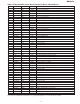
1 REC OUT Channel 1 REC OUT terminal. Useable for spare input terminal.
2 IN A1
3 IN B1
Channel 1 input terminal.
4 IN C1
5 IN D1
6 TONEH1 Channel 1 treble frequency control terminal.
7 TONEL1 Channel 1 bass frequency , gain control terminal.
8 OUT1 Channel 1 output terminal.
9 GND GND.
10 VDD + Power.
11 CONT Microcomputer data input terminal.
12 VSS – Power.
13 OUT1 Channel 2 output terminal.
14 TONEL2 Channel 2 bass frequency , gain control terminal.
15 TONEH2 Channel 2 treble frequency control terminal.
16 IN A2
17 IN B2
Channel 2 input terminal.
18 IN C2
19 IN D2
20 REC OUT Channel 1 REC OUT terminal. Useable for spare input terminal.
ICP11 VHiM62439SP-1: Audio Processor (M62439SP)
Pin No.
Function
Terminal Name
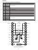
Figure 72 BLOCK DIAGRAM OF IC
REC OUT 1 REC OUT 2Rec out SW
Input SW
Monophonic SW
5K 5K
30K
2.4K2.4K
21.6K
21.6K
46K46K
30K
MUTE
Volume
Treble
boost
Bass
boost
120
INA1 INA2
219
INB1 INB2
318
INC1 INC2
417
IND1 IND2
516
TONEH1 TONEH2
615
TONEL1 TONEL2
714
OUT1 OUT2
813
GND VSS
912
VDD CONT
10 11
Control Logic