MD-MT180 SERVICE MANUAL No. S4224MDMT180S PORTABLE MINIDISC RECORDER MODEL MD-MT180(S) • In the interests of user-safety the set should be restored to its original condition and only parts identical to those specified be used. CONTENTS Page SPECIFICATIONS ................................................................................................................................................................. 2 NAMES OF PARTS ........................................................................
MD-MT180 FOR A COMPLETE DESCRIPTION OF THE OPERATION OF THIS UNIT, PLEASE REFER TO THE OPERATION MANUAL. SPECIFICATIONS Power source: DC 1.2 V: DC 5 V: DC 1.5 V: DC 4.5 V: Power consumption: Output power: 7 W (AC adaptor) RMS: 20 mW (10 mW + 10 mW) (0.2 % T.H.D.) Approx. 3.5 hours (90 %) Approx. 5.5 hours (fully charged) (When using the AC adaptor included with the unit) Width: 3" (76 mm) Height: 29/32" (22.9 mm) Depth: 3-9/32" (83 mm) 0.33 lbs.
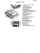
MD-MT180 NAMES OF PARTS 1 7 5 6 4 2 8 3 9 10 13 11 12 15 16 17 14 18 19 20 25 26 27 28 21 22 23 24 –3– 1. Battery Case Connection Terminals 2. 5 V DC Input Jack 3. Optical/Line Input Jack 4. Earphones/Line Output Jack 5. Record/Track Mark Button 6. Menu/Charge Button 7. Bass/Delete Button 8. Enter/Fast Play/Synchro Button 9. Volume/Cursor/Fast Forward/Fast Reverse/ Recording Level/ Name Select Button 10. Open Lever 11. Stop/Power Off/Hold Button 12. Rechargeable Battery Cover 13.
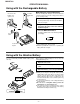
MD-MT180 OPERATION MANUAL Using with the Rechargeable Battery ■ Charging the rechargeable battery Insert the – side first. Do not force the battery cover open too far. When the rechargeable battery is used for the first time or when you want to use it after a long period of disuse, be sure to charge it fully. 1 Insert the rechargeable battery. A rechargeable battery other than the AD-N55BT cannot be charged.
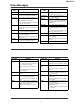
MD-MT180 Error Messages ERROR MESSAGES MEANING BATT ENPTY ● The battery has run down. BLANK MD ● Nothing is recorded. Can't COPY ERROR MESSAGES Can'tSTAMP (Replace the disc with a recorded disc.) Can'tWRITE ● You tried to record from a copy prohibited MiniDisc. ● Cannot save the TOC information correctly to a MiniDisc. DEFECT! ● The disc is scratched. (If the recorded sound is not right, retry recording or replace the disc with a recordable one.
MD-MT180 MiniDisc System Limitations The unit may have the following symptoms when recording or editing. The unit is not out of order. SYMPTOM LIMITATIONS "DISC FULL" or "TOC FULL" appears even though the MiniDisc still has recording time left. More than 255 tracks (maximum) cannot be recorded regardless of the recording time. If the MiniDisc is recorded or edited repeatedly or if it has scratches (recording skips scratched parts), you may not be able to record the maximum tracks above.
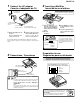
MD-MT180 1 2 Connect the AC adaptor Conecte el adaptador de CA Inserting a MiniDisc Inserción de un minidisco AC 120V, 60 Hz 1 Insert according to the direction of the arrow. 120V CA, 60Hz 2 4 Insértelo de acuerdo con la dirección de la flecha. 3 1 To an AC outlet A un tomacorriente de CA To the DC IN 5V jack A la toma DC IN 5V 2 1 Plug the AC adaptor into the 1 Slide the OPEN lever to re- 3 Insert a MiniDisc as shown. Insert the plugs firmly. lease the compartment door.
MD-MT180 Recording / Grabación Check that the unit is connected to the stereo system. Compruebe que el aparato esté conectado al sistema estéreo. 5 Press the MENU/CHRG button repeatedly to select the "REC MODE". Pulse repetidamente el botón MENU/CHRG para seleccionar "REC MODE". 6 Press the ENTER/SYNC button. Pulse el botón ENTER/SYNC. 7 Press the MENU/CHRG button repeatedly to select recording mode. Pulse repetidamente el botón MENU/CHRG para seleccionar el mode de grabación.
MD-MT180 DISASSEMBLY Cares before disassembling When assembling the machine after disassembling or repair, observe the following requirements so as to ensure safety and performance. 1. Remove the batteries from the machine, and take out the mini-disc. 2. When assembling after repair, be sure to position the wires in the same location. Use the specified screws to fix the cabinet and the mechanism unit.
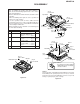
MD-MT180 REMOVING AND REINSTALLING THE MAIN PARTS Remove the mechanism according to the disassembling methods 1 to 4. (See Page 9.) (A2) x2 ø1.4 x1.8mm How to remove the magnetic head (See Fig. 10-1.) 1. Remove the solder joints (A1) x 2 of the head flexible plate. 2. Remove the screws (A2) x 2 pcs. of the magnetic head. Note: Mount carefully so as not to damage the magnetic head. MD Mechanism Magnetic Head Solder Joints (A1)x2 How to remove the spindle motor (See Fig. 10-2.) 1.
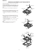
MD-MT180 How to remove the Lift motor (See Fig. 11-1.) 1. Remove the solder joints (D1) x 2 of the lift motor lead wire. 2. Remove the screw (D2) x 1 pc., and remove the lift motor. Note: Take care so that the motor gear is not damaged. (If the gear is damaged, noise is caused.) Lift Motor SolderJoints (D1)x2 How to reinstall the optical pickup (See Fig. 11-2.) 1. Remove the screw (E1) x 1 pc., and remove the spring. 2. Slowly raise the optical pickup. (D2) x1 ø1.
MD-MT180 ADJUSTMENT Test disc MD adjustment needs two types of disc, namely recording disc (low reflection disc) and playback-only disc (high reflection disc). Type Parts No.
MD-MT180 • Whenever the MENU button is pressed in the continuous playback mode, the indication changes as follows. * Pre-mastered disc Continuous playback (SUBQ address indication) [ S Q ] Operation in each TEST mode 1. AUTO1 Mode • When the STOP button is pressed while the AUTO1 menu appears or during automatic adjustment, the mode changes to the TEST mode stop state. At this time the adjustment value is not output. • Be sure to adjust, using the specified disc MMD-213A or MMD-212.
MD-MT180 5. NORMAL Mode • When the STOP button is pressed while the NORMAL menu appears, the mode changes to the TEST mode stop state. • Indication during operation Indication of memory capacity on main unit LCD [ ] + Level meter : Internal mode : Address (Cluster section) : Address (Sector section) • Selection of sound volume, BASS, etc. is possible (without indication) • Recording is also possible.
MD-MT180 EEPROM (IC402) writing procedure 2. Temperature reference setting method 1. Procedure to replace EEPROM and write initial value of microcomputer in EEPROM [1] Measurement, calculation and setting procedure (1) Set the TEST mode. • Set TEST 1, 0 = '01', and turn on power (or set PLAY ON in standby state). (2) Press the MENU button, ENTER button and Play button to start the test mode. (3) Start the EEPROM mode 'Temp' menu.
MD-MT180 EEPROM DATA LIST (EEPROM version c) Sled setting (Continued) TEMP setting Item display Item display T M _ _ Set values Calculate values Focus setting Item display Set values F G 1 _ 40H F Z H _ F L n _ EDH 09H F L p _ F T s _ 06H 18H F S B _ F T B _ 40H 28H T O 1 _ T O R _ 50H 58H 0EH 1CH B P E _ B P W _ 71 75 H B P 1 _ B R E _ 33 95 H B R W _ S R S _ 33H 3CH H H Bass setting Item display Tracking setting Item display Set values S K E _ S D E _ Set values B 1 A _ B
MD-MT180 Test Mode Change Chart Test Mode Menu TEST : Test Mode STOP FAST REVERSE FAST FORWARD Slide internal periphery move Slide external periphery move BASS FAST REVERSE AUTO1 FAST FORWARD : Pre-auto adjustment menu FAST REVERSE AUTOJ : Auto 1 & 2, Focus balance adjustment menu FAST FORWARD FAST REVERSE AUTO2 FAST FORWARD T PLAY FAST FORWARD T : ATT auto adjustment menu FAST REVERSE REC FAST FORWARD : ATT manual adjustment menu FAST REVERSE MANU1 FAST FORWARD : Pre-adjustment value
MD-MT180 ATT Auto Adjustment AUTO2 : ATT auto adjustment menu PLAY AT2 : During ATT auto adjustment Adjustment error ADJ. NG Normal end : ATT adjustment error (adjustment value output) : ATT adjustment normal end (adjustment value output) ADJ.
MD-MT180 Continuous Rrecord • Continuous record from the current pickup position T REC : Continuous record menu PLAY : Continuous record # # # #: Address • Continuous record playback from any address AP# # # # T REC : Continuous record menu PLAY : Start address setting Ad 0 0 3 2 PLAY : Continuous record # # # #: Address AP# # # # * When the [STOP ] button is pressed in specific menu, the "TEST MODE STOP" state is set.
MD-MT180 Error History Display • Error history clear E DATA : Error history display menu MENU CLEAR : Error history clear • Error history display E DATA : Error history display menu PLAY E0§§ FAST FORWARD FAST REVERSE : Error history 0 display § § : Error code : Error history 1 display § § : Error code E1§§ FAST FORWARD FAST REVERSE : Error history 2 display § § : Error code E2§§ FAST FORWARD FAST REVERSE : Error history 3 display § § : Error code E3§§ FAST FORWARD FAST REVERSE : Error h
MD-MT180 Focus Setting Focus : Focus setting menu PLAY FG1 FAST FORWARD FAST REVERSE FZH FAST FORWARD FAST REVERSE FLn FAST FORWARD FAST REVERSE FLp FAST FORWARD FAST REVERSE FTS FAST FORWARD FAST REVERSE FSB FAST FORWARD FAST REVERSE FTB FAST FORWARD FAST REVERSE TO1 FAST FORWARD FAST REVERSE TOR * When the [STOP ] button is pressed in specific menu, the "TEST MODE STOP" state is set.
MD-MT180 Tracking Setting T r a c k : Tracking setting menu PLAY TG1 FAST FORWARD FAST REVERSE FAST FORWARD TBo FAST FORWARD FAST REVERSE FAST FORWARD FAST REVERSE FAST FORWARD FAST REVERSE FAST FORWARD FAST REVERSE FAST FORWARD FAST REVERSE FAST FORWARD FAST REVERSE FAST FORWARD FAST REVERSE TOG SCt FAST FORWARD FAST REVERSE TOP TDt FAST FORWARD FAST REVERSE THG TDo FAST FORWARD FAST REVERSE THP TKt FAST FORWARD FAST REVERSE K10 TKo FAST FORWARD FAST REVERSE JPI TBt FAST
MD-MT180 TEMP Setting Temp : Temp setting menu PLAY TM§§ FAST FORWARD T p i n : TEMP reference : Reference § § : Temperature code FAST REVERSE : TEMP A/D input value : Measurement value * When the [STOP ] button is pressed in specific menu, the "TEST MODE STOP" state is set. * When the [MENU] button operation is performed in the specific state, the menu changes to "TEMP SETTING menu". * In the specific state the setting changes in the range of "00h to FFh" when the [VOL.+/–] button is pressed.
MD-MT180 Control Setting CTRL : Control setting menu PLAY CT0 FAST FORWARD FAST REVERSE CT1 FAST FORWARD US2 FAST REVERSE FAST REVERSE CT2 FAST FORWARD FAST REVERSE FAST REVERSE CT3 FAST FORWARD FAST REVERSE FAST REVERSE FAST REVERSE FAST REVERSE FAST REVERSE FAST REVERSE FAST REVERSE FAST REVERSE FAST REVERSE FAST REVERSE FAST REVERSE FAST REVERSE FAST REVERSE FAST REVERSE FAST REVERSE FAST REVERSE FAST REVERSE FAST REVERSE FAST REVERSE FAST REVERSE FAST REVERSE FAST REVERS
MD-MT180 MD ERROR MESSAGE DISPLAY CONTENT LIST Display content Error code Error content Can' t READ* Readout of the information is not completed. Can' t READ* Readout of the TOC information is not completed. Can' t READ* Readout of the U-TOC information is not completed. Can't LOCK The EJECT lever cannot be locked. Er-MD41 Judged it abnormal by the U-TOC write test.
MD-MT180 NOTES ON SCHEMATIC DIAGRAM • Resistor: To differentiate the units of resistors, such symbol as K and M are used: the symbol K means 1000 ohm and the symbol M means 1000 kohm and the resistor without any symbol is ohm-type resistor. Besides, the one with “Fusible” is a fuse type. • Capacitor: To indicate the unit of capacitor, a symbol P is used: this symbol P means micro-micro-farad and the unit of the capacitor without such a symbol is microfarad.
M901 SPINDLE MOTOR M902 SLED MOTOR M903 LIFT MOTOR M M M +2.5V +2.5V IC651 LB1930M MOTOR DRIVER +2.5V IC101 IR3R58M RF SIGNAL PROCESSOR Figure 27 BLOCK DIAGRAM – 27 – +4.5V BATTERY (1.2V) CHARGING TERMINAL(1.5V) 4.5V REGULATOR IC873 6204B45M +2.5V FG IC253,260,809 XP04313 IC256 XP04315 IC258,259,892 XP04501 Q250,Q251,Q257 IC251 FTD2017 N-CH MOS FET IC255 NJM022V OPE AMP. IC257 S80808LN RESET SPIN VCCMICOM +2.5V REGULATOR IC902 62FP1602 IC841 6372C251 2.5V UP CONVERTER VGBATT F841 0.
MD-MT180 MAIN PWB-A R206 100K +B VCCDRAM CK200 L202 10µH C201 10/6.3 TP407 R413 1K PLVO TP415 TP401 TEMP R424 22K R423 22K DINT AURESET 1 TP441 TP610 +B 3 2 4 D431 MA132WK IC431 S80820LN C431 0.47 R431 330K 2 VDD 4 VSS 3 RESET M903 LIFT MOTOR D461 RB731U 3 4 2 5 1 6 • NOTES ON SCHEMATIC DIAGRAM can be found on page 26. • The numbers 1 to 15 are waveform numbers shown in page 44.
MD-MT180 R456 R457 5.6K 8.2K HKEY2 R458 18K HPLAY DADATA ADDATA DFCK HKEY1 STOP DSPDAT TP481 DSPSCK R481 TP482 DSPSTB 33K C482 TP483 0.01 TP484 TP485 R483 R482 18K 18K TP487 1 R718 1K C711 100P (CH) R728A 10K C714 1 C712 100P(CH) C733 0.1 C734 0.1 AGND C701 10/6.3 R701 100 D496 MA8075M IC703 IR3R59N AUDIO AMP. 4 L-CH 2 R-CH 3 1 J703A HEADPHONES HREC HPLAY R467 22K 7 STOP D281 MA111 +B PCNT2 PLVBAT CHGON PLVON CHGCNT TP805 L801 100MHZ R810 1 VCCBATT 4 2 VDD 3 C254 0.
MD-MT180 SUB PWB-B D2 1SS385 C3 0.1 D1 1SS385 CK13A 8 7 6 5 R1 10K 1 2 3 4 5 6 7 1 2 3 4 IC2 TC7W74FK 1413121110 9 8 A VCC B QH QA QG QB QF QC QE QD Q GND CK IC1 74VHC164FT C2 0.1 CK VCC D PR Q CL GND Q A B MAIN PWB VERSION C , MAIN PWB-A R2 10K C1 100P (CH) B CKG CK14 CK16 CKV CK13 +B C734 0.1 AGND LOUT LIHP ROUT RI R762 100K LPF LLPFO C492 1 R– R+ L+ LPF L– RIN ATT AMPuGAIN SEL. LHPVEE C753 1 C703 0.01 R766 15 C761 2.
MD-MT180 D2 1SS385 8 7 6 5 R1 10K CK VCC D PR Q CL GND Q 1413121110 9 8 1 2 3 4 5 6 7 1 2 3 4 IC2 TC7W74FK C3 0.1 D1 1SS385 A VCC B QH QA QG QB QF QC QE QD Q GND CK IC1 74VHC164FT C2 0.
MD-MT180 A MAIN PWB VERSION B X0021AWZZ SUB PWB-B is added to this version PWB. SUB PWB-B is shown in page 36,37.
MD-MT180 MAIN PWB VERSION B X0021AWZZ SUB PWB-B is added to this version PWB. SUB PWB-B is shown in page 36,37.
MD-MT180 A MAIN PWB VERSION C X0021AWZZ SUB PWB-B is added to this version PWB. SUB PWB-B is shown in page 36,37.
MD-MT180 MAIN PWB VERSION C X0021AWZZ SUB PWB-B is added to this version PWB. SUB PWB-B is shown in page 36,37.
MD-MT180 A MAIN PWB VE SUB PWB-B is added to B SW403 LID OPEN 1 4 TP726 2 13 IC703 15 CK418 20 3 C TP665 15 14 13 10 5 12 1 24 20 5 6 CP7 IC703 15 10 1 13 12 D 7 CK203 16 CK202 CK205 15 76 85 90 80 10 75 8 E CK403 70 65 IC401 4 1 60 4 40 CK809 1 3 SW401 EJECT 2 2 1 55 35 9 IC501 XL401 5 IC255 45 51 3 50 5 8 4 CK102 3 1 4 6 6 1 10 5 15 45 IC101 20 4 48 8 5 1 35 37 36 TP201A 1 4 6 4 6 1 6 3 4 1 6 3 1 4 6 3 4 3 1 1 4
MD-MT180 C3 CKV 14 SUB PWB-B 8 D1 C2 IC1 MAIN PWB VERSION B , C CK13A CK13 CK14 8 5 D2 10 R1 IC2 5 SUB PWB-B is added to this version PWB.
MD-MT180 MAIN PWB VERSION X X0035AWZZ A J701 OPTICAL/LINE-IN J703A HEADPHONES SW403 LID OPEN TP705 TP701 TP711 TP703 TP727 TP726 TP704 TP725 TP722 TP712 TP721 B TP724 J801 DC-IN 5V TP801 TP723 TP702 SW601 TP665 DISC PROTECT TP706 TP708 TP802 TP714 TP707 TP713 TP729 TP806 TP455 TP772 TP459 TP6 R857 TP482 IC771 C851 TP656 Q851 C863 C840 TP661 L851 C1 R2 E 51 70 76 TP417 C3 D2 D1 R1 TP115 C204 C201 40 IC201 TP122 35 95 TP132 TP131 TP130 15 24 1 25 TP144
MD-MT180 MAIN PWB VERSION X X0035AWZZ J703A HEADHONES J701 OPTICAL/LINE-IN SW403 LID OPEN C171 R403 C753 D496 C754 R757 R761 R754 R461 C510 CK203 C511 R501 36 C131 C551 R261 R262 R250 R253 R255 D251 4 D281 1 3 5 1 IC251 6 4 2 R285 6 4 C612 C100 1 6 3 4 3 1 4 R256 R293 Q250 Q251 R287 1 6 3 4 6 1 R139 R288 3 R281 3 IC258 4 C259 IC256 6 3 1 4 C252 6 C106 R272 8 3 C253 R254 C254 C255 R266 IC431 R269 L204 C502 37 R252 1 CK100 C114 35 8
MD-MT180 MAIN PWB VERSION D X0021AWZZ A J701 OPTICAL/LINE-IN J703A HEADPHONES SW403 LID OPEN TP705 TP701 TP711 TP703 TP727 TP726 TP704 TP712 TP721 B TP724 J801 DC-IN 5V TP801 TP723 TP725 TP722 TP702 SW601 TP665 DISC PROTECT TP706 TP708 TP802 TP714 TP707 TP713 TP729 TP806 TP455 TP772 TP459 TP6 R857 IC771 C851 TP656 Q851 C863 C840 TP661 L851 C837 R222 75 51 70 76 TP417 65 60 C845 55 TP115 95 30 TP106 TP102 TP114 TP131 TP130 TP132 10 100 15 25 1 TP201 TP108
MD-MT180 MAIN PWB VERSION D X0021AWZZ J703A HEADHONES J701 OPTICAL/LINE-IN SW403 LID OPEN 24 30 R403 C753 C754 C510 CK203 C511 R501 35 37 36 C131 C551 R261 R262 R250 C252 D251 4 4 3 D281 1 3 5 1 IC251 6 4 2 R285 6 4 C612 6 3 4 1 R256 R293 Q250 Q251 C864 R139 R287 1 6 3 4 6 1 CHASSIS GND C100 1 3 4 R288 3 6 1 4 6 1 C106 R272 8 3 R255 R252 R253 8 C253 R254 C254 C255 5 C259 IC256 C111 L204 C502 XL401 R267 R406 IC255 1 4 SW401 EJECT 2
MD-MT180 TO MAIN PWB P33,P35,P39,P41 8-C,D CN601 M902 SLED MOTOR MAGNETIC HEAD (20) TO MAIN PWB P33,P35,P39,P41 9-C,D MECHANISM FLEXIBLE PWB (19) CN451 M901 SPINDLE MOTOR M903 LIFT MOTOR KEY SWITCH FLEXIBLE PWB (228) LCD UNIT (229) OPTICAL PICKUP (1) CN101 P33,P35,P39,P41 8,9-E,F TO MAIN PWB CN482 P33,P35,P39,P41 9,10-C,D TO MAIN PWB Figure 42 WIRING SIDE OF P.W.
MD-MT180 VOLTAGE IC101 PIN NO. 1 2 3 4 5 6 7 8 9 10 11 12 13 14 15 16 17 18 19 20 21 22 23 24 25 26 27 28 29 30 31 32 33 34 35 36 37 38 39 40 41 42 43 44 45 46 47 48 VOLTAGE 0.27V 0.27V 0.27V 0.27V 1.31V 1.31V 1.31V 1.31V 1.31V 1.31V 1.31V 1.31V 1.31V 1.31V 1.31V 1.31V 1.31V 1.31V 1.31V 1.31V 1.31V 1.31V 1.31V 0.28V 1.49V 0V 0V 2.61V 2.61V 2.36V 0V 1.31V 1.31V 0.26V 1.08V 0V 1.31V 1.31V 0.27V 2.61V 1.53V 0V 1.31V 0.19V 0.29V 1.31V 0.29V 0.51V IC202 PIN NO.
MD-MT180 WAVEFORMS OF MD CIRCUIT T Stopped CH1=1mV DC 10:1 1 CH2=500mV DC 10:1 CH3=5V DC 10:1 TP208 (FEMON) 5 IC501(9) (SDTi) 6 IC501(12) (SCLK) TP120 (F+) CK206 (CIN) 4 CK204 (FOK) 7 T Stopped CH1=1V DC 10:1 9 CH2=2V DC 10:1 CH3=500mV DC 10:1 1994 / 12 / 16 01:03:40 2ms/div (2ms/div) ENV TP201 (EFMMON) 1 TP210 10 (TEMON) IC501(10) (LRCK) 8 T T 2 11 3 3 TP209 (TOTMON) IC501(11) (MCLK) 4 =Filter= Smoothiing : OFF BW : FULL =Offset= CH1 : 0.00V CH2 : 0.000V CH3 : 0.
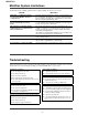
MD-MT180 TROUBLESHOOTING It is advisable to use the TEST mode (refer to Error Data Display Mode, P14) indicating the causes of troubles before starting repair. Causes of operation errors (up to 10 errors) are recorded as error codes. This information is useful for repair. When MD playback does not function When the objective lens of the optical pickup is dirty, this section may not operate. Clean the objective lens, and check the playback operation.
MD-MT180 • Audio playback circuit Although the playback time display is acting., no sound is given during playback in the normal mode. Is audio waveform output from IC501 pins 15 and 16? No Check IC201 pins 70 to 72, pin 74 and IC501 pins 9, 10, 11, 12. Yes Is audio waveform output from IC703 pins 8 and 17. No Check the pins 4 and 21 of IC703. Yes Is audio waveform output from J703A pins 2 and 3.
MD-MT180 • Recording/playback operation. Insert a low reflection disc, and ascertain audio output by normal playback, and then set TEST REC mode. Change MSL from 00H to 80H by the control setting of EEPROM. After completing the operation, return in to 00H. Does the head move down, failing to start record even when the continuous record mode is set after address ? No Yes Does the RF waveform appear at TP201 when recording/ Playback is performed.
MD-MT180 FUNCTION TABLE OF IC IC401 RH-iX0484AWZZ :System Microcomputer (IX0484AW) (1/2) Main PWB Version B,C,X IC401 RH-iX0529AWZZ :System Microcomputer (IX0529AW) (1/2) Main PWB Version D Pin No.
MD-MT180 IC401 RH-iX0484AWZZ :System Microcomputer (IX0484AW) (2/2) Main PWB Version B,C,X IC401 RH-iX0529AWZZ :System Microcomputer (IX0529AW) (2/2) Main PWB Version D Pin No.
MD-MT180 IC201 VHiLR378161-1 :Endec/Servo/Atrac (LR378161) System LSI expansion output port (LR378161) Pin No. Port Name Terminal Name Input/Output Function Remarks 56 EXPORT0 LEDON1 Output LED ON/OFF 'H':ON"L":OFF 57 EXPORT1 LDCNT1 Output Recording head raising-lowering control output 1 See the separate table *3. 58 EXPORT2 LDCNT2 Output Recording head raising-lowering control output 2 (Open) 59 EXPORT3 EMPH1 Output Audio emphasis control output 1 See the separate table *2.
MD-MT180 IC601 VHiLV8201W+-1 :PWM Driver (LV8201W)(1/2) Pin No. Terminal Name Function 1 COM Spindle motor COM point connection terminal. 2 IN1F H bridge 1 logic input terminal. Output from pins 9 and 7. 3 IN1R 4 IN2F 5 IN2R 6 GND2 GND terminal in the MOS circuit section. 7 OUT1R H bridge 1 reverse output terminal. 8 VS1 H bridge 1 motor power supply terminal. The capacitor is connected to the GND terminal. 9 OUT1F H bridge 1 forward output terminal.
MD-MT180 IC601 VHiLV8201W+-1 :PWM Driver (LV8201W)(2/2) Pin No. Terminal Name Function 44 VCC2 Terminal for supplying power to MOS circuit. Used by connecting to VCC1 terminal (pin 20). 45 IN3 Half bridge logic input terminal. Output from pin 36. 46 S3 Logic input terminal in 3-phase thread section. Output from pins 42, 40, and 38. 47 S2 48 S1 49 CP2 Output terminal for charge pump booster pulse. The capacitor is connected between this terminal and CPC2 terminal (pin 52).
MD-MT180 IC202 RH-iX2824AFZZ: 16M Bit D-RAM (IX2824AF) Function Terminal Name Pin No. 1 Vcc Power supply (2.6V) 2 I/O1 Data input/data output 3 I/O2 Data input/data output 4 WE Write enable 5 RAS Low address strobe 6* NC Not connected 7 A10 Address input 8-11 A0-A3 Address input 12 Vcc Power supply (2.
MD-MT180 —MEMO— – 54 –
MD-MT180 PARTS GUIDE PORTABLE MINIDISC RECORDER MODEL MD-MT180(S) “HOW TO ORDER REPLACEMENT PARTS” To have your order filled promptly and correctly, please furnish the following information. 1. MODEL NUMBER 2. REF. No. 3. PART NO. 4. DESCRIPTION For U.S.A. only Contact your nearest SHARP Parts Distributor to order.
MD-MT180 NO.
MD-MT180 NO. PRICE RANK PART CODE DESCRIPTION NO.
MD-MT180 NO. R819 R831,832 R844 R850 R853 R854 R855 R856 R857 R871 R891 R892 R920 PRICE RANK PART CODE VRS-CY1JB223J VRS-CY1JB184F VRS-CY1JB470J VRS-CY1JB104J VRS-CY1JB274J VRS-CY1JB103J VRS-CY1JB394F VRS-CY1JB335J VRS-CY1JB334F VRS-CY1JB104J VRS-CY1JB473J VRS-CY1JB103J VRS-CY1JB104J J J J J J J J J J J J J J DESCRIPTION AA AA AA AA AA AA AA AA AA AA AA AA AA 22 kohms,1/16W 180 kohms,1/16W 47 ohms,1/16W 100 kohm,1/16W 270 kohms,1/16W 10 kohm,1/16W 390 kohms,1/16W 3.
MD-MT180 502x2 A 20 501 13 503 1 B 12 18 505x3 M901 19 15 17 C 503 501x2 M903 3 506 D M902 9 16 4 E 2 10 11 504 F G 5 8 7 H 6 1 2 14 3 4 Figure 4 MD MECHANISM EXPLODED VIEW –4– 5 6
MD-MT180 205 A MD MECHANISM 225 B 603x2 210 209 201 222 605 604 212 C 215 216 604 213 206 220 226x2 219 229 D PWB-A 227 231 224 218 228 E 601 607 223 230 601 211 F 221 208 214 217 203 603 608 609 G 603 608 606x2 202 207 H 204 606 1 2 3 4 Figure 5 CABINET EXPLODED VIEW –5– 5 6
MD-MT180 PACKING OF THE SET (FOR U.S.A. ONLY) Pad,Operation Manual SPAKZ0490AWZZ Earphones Connecting Cord, RCA Type Quick Guide Battery Case Operation Manual Battery Carring Case Bag,Polyethylene SSAKH0033AWZZ AC Adaptor Rechargeable Battery Label,SER.No.,Set TLABN0092AWZZ Pad,Unit SPAKA0336AWZZ Packing Case SPAKC1341AWZZ Label,Bar Code TLABR1254AWZZ Label,SER.No.
MD-MT180 –MEMO–
MD-MT180 –MEMO–
MD-MT180 COPYRIGHT © 2002 BY SHARP CORPORATION ALL RIGHTS RESERVED. No part of this publication may be reproduced, stored in a retrieval system, or transmitted in any from or by any means, electronic, mechanical, photocopying, recording, or otherwise, without prior written permission of the publisher.