
Service manual


– 10 –
MD-MT180
REMOVING AND REINSTALLING THE MAIN PARTS
Remove the mechanism according to the disassembling meth-
ods 1 to 4. (See Page 9.)
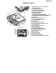
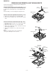
How to remove the magnetic head (See Fig. 10-1.)
1. Remove the solder joints (A1) x 2 of the head flexible plate.
2. Remove the screws (A2) x 2 pcs. of the magnetic head.
Note:
Mount carefully so as not to damage the magnetic head.
How to remove the sled motor (See Fig. 10-3.)
1. Remove the stop washer (C1) x 1 pc., and remove the drive
gear (C2) x 1 pc.
2. Remove the solder joints (C3) x 3 of flexible PWB.
3. Remove the screws (C4) x 2 pcs., and remove the sled
motor and the left bracket.
4. Remove the screw (C5) x 1 pc., and remove the right
bracket.
Note:
Take care so that the motor gear is not damaged.
(If the gear is damaged, noise is caused.)
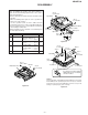
How to remove the spindle motor (See Fig. 10-2.)
1. Remove the solder joints (B1) x 4 of flexible PWB.
2. Remove the screws (B2) x 3 pcs., and remove the spindle
motor.
MD Mechanism
Spindle
Motor
Solder Joints
(B1)x4
(B2) x3
ø1.4 x3mm
MD Mechanism
Solder Joints
(C3)x3
(C4) x2
ø1.4 x1.5mm
(C5) x1
ø1.7 x3.5mm
Stop Washer
(C1)x1
Drive Gear
(C2)x1
Right
Bracket
Left
Bracket
Cartridge Holder
Sled Motor
(A2) x2
ø1.4 x1.8mm
MD Mechanism
Magnetic Head
Solder Joints
(A1)x2
Figure 10-1
Figure 10-2
Figure 10-3