MD-MT80W/90W/90/90C SERVICE MANUAL No. S4123MDMT80W/ PORTABLE MINIDISC RECORDER Illustration: MD-MT80W MODEL Illustration: MD-MT90W/90/90C MD-MT80W(S) MD-MT90W(S) MD-MT90(S) MD-MT90C(S) • In the interests of user-safety the set should be restored to its original condition and only parts identical to those specified be used. CONTENTS Page SAFETY PRECAUTION FOR SERVICE MANUAL (MD-MT80W/90W ONLY) .....................................................................
MD-MT80W/90W/90/90C SAFETY PRECAUTION FOR SERVICE MANUAL (MD-MT80W/90W ONLY) Precaution to be taken when replacing and servicing the Laser Pickup. Laser Diode Properties ● Material: GaAlAs ● Wavelength: 785 nm ● Pulse time: Read mode: 0.8 mW Continuous Write mode: max 10 mW 0.5S min cycle 1.5S Repetition THE AEL (ACCESSIBLE EMISSION LEVEL) OF THE LASER POWER OUTPUT IS LESS THAN CLASS 1 BUT THE LASER COMPONENT IS CAPABLE OF EMITTING RADIATION EXCEEDING THE LIMIT FOR CLASS 1.
MD-MT80W/90W/90/90C AC ADAPTOR AND PLUG (MD-MT80W/90W ONLY) PADPA6049AWZZ PADPA5052AWZZ PADPA5051AWZZ QPLGA0004AWZZ –3– PADPA5050AWZZ
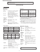
MD-MT80W/90W/90/90C FOR A COMPLETE DESCRIPTION OF THE OPERATION OF THIS UNIT, PLEASE REFER TO THE OPERATION MANUAL. SPECIFICATIONS MD-MT80W/90W ■ General Battery life: Power source: DC 5V: AC adaptor (AC 110-240V, 50/60 Hz) DC 1.5V: Commercially available, "AA" size (LR6), alkaline battery x 1 DC 1.2V: Optional rechargeable Nickel-Metal Hydride battery (AD-N70BT) x 1 DC 4.5V: Optional car adaptor, AD-CA20X(for cars with a 12 - 24V DC negative earth electrical system) Power consumption: 0.
MD-MT80W/90W/90/90C MD-MT90/90C ■ General Battery life: Power source: DC 1.2V: Rechargeable Nickel-Metal Hydride battery (AD-N70BT) x 1 DC 5V: AC adaptor (AC 120V, 60 Hz) DC 1.5V: Commercially available, "AA" size (LR6), alkaline battery x 1 DC 4.5V: Optional car adaptor, AD-CA20X(for cars with a 12 - 24V DC negative ground electrical system) Power consumption: 7 W (AC adaptor) Output power: RMS; 20 mW (10 mW + 10 mW) (0.2% T.H.D.) Charging time: Approx. 3.
MD-MT80W/90W/90/90C ACCESSORIES MD-MT80W AC Adaptor x 1 or Headphones x 1 or or Connection Cable (for analogue recording) x 1 Notes: ● Parts and equipment mentioned in this operation manual other than those detailed above are not included. ● The AC adaptor may be different from the one in the drawing.
MD-MT80W/90W/90/90C NAMES OF PARTS ■ Main unit 1. 5V DC Input Jack 2. Optical/Line Input Jack 3. Microphone Input Jack 4. Bass/Delete Button 5. Edit/Auto Mark/Time Mark Button 6. Display/Character Select Button 7. Mode/Charge Button 8. Record/Track Mark Button 9. Volume/Cursor/Fast Forward/Fast Reverse/ Recording Level/Name Select Button 10. Play/Pause Button 11. Stop/Power Off/Hold Button 12. Enter/Fast Play/Synchro Button 13. Remote Control/Headphones/Line Output Jack 14. Open Lever 15.
MD-MT80W/90W/90/90C NAMES OF PARTS ■ Display panel 1. Level Meter 2. Record Indicator 3. Remaining Recording Time Indicator 4. Monaural Long-Play Mode Indicator 5. Repeat Indicator 6. TOC Indicator 7. Synchro Recording Indicator 8. Disc Mode Indicator 9. Disc Name Indicator 10. Track Name Indicator 11. Total Track Number Indicator 12. Fast Play Indicator 13. Battery Indicator 14. Random Indicator 15. Track Number Indicator 16. Character/Time Information Indicator ■ Remote control unit (MD-MT90W/90/90C) 1.
MD-MT80W/90W/90/90C MD-MT90/90C Battery Power ■ Charging the rechargeable battery When the rechargeable battery is used for the first time or when you want to use it after a long period of disuse, be sure to charge it fully. 1 Insert the rechargeable battery. A rechargeable battery other than the one supplied or the optional one (AD-N70BT) cannot be charged. 2 Plug the AC adaptor into the AC outlet, and then insert the plug on the other end into the DC IN 5V jack. 3 Press the MODE/CHRG button.
MD-MT80W/90W/90/90C Error Messages ERROR MESSAGES MEANING REMEDY BATT EMPTY ● The battery is run down. ● Charge the rechargeable battery or replace the alkaline battery (or use the AC adaptor for power). BLANK MD ● Nothing is recorded. ● Replace the disc with a recorded disc. Can't COPY ● You tried to record from a copy prohibited MiniDisc. ● Record using the analog cable. Can't EDIT ● A track cannot be edited. ● Change the stop position of the track and then edit it.
MD-MT80W/90W/90/90C MiniDisc System Limitations The unit may have the following symptoms while recording or editing. The unit is not out of order. SYMPTOM LIMITATIONS "DISC FULL" or "TOC FULL" appears even though the MiniDisc still has recording time left. More than 255 tracks (maximum) cannot be recorded regardless of the recording time. If the MiniDisc is recorded or edited repeatedly or if it has scratches (recording skips scratched parts), you may not be able to record the maximum tracks above.
MD-MT80W/90W/90/90C MD-MT90 ONLY 1 Inserting a MiniDisc Inserción de un minidisco Quick Guide / Guía rápida PORTABLE MINIDISC RECORDER GRABADOR/REPRODUCTOR MINIDISC PORTÁTIL 2 1 4 3 MODEL/MODELO MD-MT90 Insert according to the direction of the arrow. Quick Setup Guide Guía rápida de configuración Insértelo de acuerdo con la dirección de la flecha. 1 Slide the OPEN lever to re- 3 Insert a MiniDisc as shown. Follow the setup procedure (1-3) before you use this unit.
MD-MT80W/90W/90/90C Recording / Grabación Preparation for use Preparación para su utilización Check that the unit is connected to the stereo system. Compruebe que el aparato esté conectado al sistema estéreo. The unit does not work if the unit is in the hold mode. El aparato no funciona si está en el modo de retención. Press the HOLD button for 2 seconds or more. Pulse el botón HOLD durante 2 o más segundos. Hold Retención Released Liberación 1 Press the REC button. Pulse el botón REC.
MD-MT80W/90W/90/90C DISASSEMBLY Cares before disassembling When assembling the machine after disassembling or repair, observe the following requirements so as to ensure safety and performance. 1. Remove the batteries from the machine, and take out the mini-disc. 2. When assembling after repair, be sure to position the wires in the same location. Use the specified screws to fix the cabinet and the mechanism unit.
MD-MT80W/90W/90/90C REMOVING AND REINSTALLING THE MAIN PARTS Remove the mechanism according to the disassembling methods 1 to 4. (See Page 14.) How to remove the spindle motor (See Fig. 15-1.) 1. Remove the solder joints (A1) x 4 of flexible PWB. 2. Remove the screws (A2) x 3 pcs., and remove the spindle motor. (A2) x3 ø1.4 x2.5mm Mechanism Flexible PWB Solder joints (A1)x4 Spindle Motor How to remove the Lift motor (See Fig. 15-2.) 1. Remove the solder joints (B1) x 2 of lift motor lead wire. 2.
MD-MT80W/90W/90/90C ADJUSTMENT Test disc MD adjustment needs two types of disc, namely recording disc (low reflection disc) and playback-only disc (high reflection disc). Type Parts No.
MD-MT80W/90W/90/90C Operation in each TEST mode 1. AUTO1 Mode • When the STOP button is pressed while the AUTO1 menu appears or during automatic adjustment, the mode changes to the TEST mode stop state. At this time the adjustment value is not output. • Be sure to adjust, using the specified disc MMD-213A or MMD-212. At this time release the EEPROM (IC402) protection. (Refer to EEPROM write procedure.
MD-MT80W/90W/90/90C 5. NORMAL Mode • When the STOP button is pressed while the NORMAL menu appears, the mode changes to the TEST mode stop state. • Indication during operation Indication of memory capacity on main unit LCD [ ] + Level meter : Internal mode : Address (Cluster section) : Address (Sector section) • Selection of sound volume, BASS, etc. is possible (without indication) • Recording is also possible.
MD-MT80W/90W/90/90C EEPROM (IC402) writing procedure 2. Temperature reference setting method 1. Procedure to replace EEPROM and write initial value of microcomputer in EEPROM [1] Measurement, calculation and setting procedure (1) Set the TEST mode. • Set TEST 1, 0 = '01', and turn on power (or set PLAY ON in standby state). (2) Start the EEPROM mode 'Temp' menu. • Key operation in order of BASS, FAST REVERSE x 2 times, PLAY , PLAY in the test mode STOP state. ' is displayed.
MD-MT80W/90W/90/90C EEPROM DATA LIST (EEPROM version d) Item display T M _ _ Set values Calculate values Focus setting Item display ADJ.
Normality completion Normality completion (During the focus balance adjustment) (During the adjustment that ATT is automatic) (During the spare style automatic adjustment) – 21 – (Adjustment completion) OK (Continuance is regenerating) It confirms that an address proceeds If you replaced EEPROM, set the EEPROM valume to the final version. (In such cases as the battery) All the supply of the power supply is turned off Indication disappears BYE STOP is pushed AP#### PLAY ADJ.
ADJ. NG Adjustment error : During ATT automatic adjustment : Preadjustment normal end (adjustment value output) : Preadjustment error (adjustment value output) : During preadjustment adjustment : Preautomatic Adjustment menu * When the [STOP ] button is pressed in specific menu, the "TEST MODE STOP" state is set. *" " represent the adjustment number as follows.
PLAY : Continuous playback (pit section) : Continuous playback (groove section) # # # # : Address : Start address setting : Continuous playback menu – 23 – MODE DISP Ad0 3 C 0 MODE DISP DISP 0950H Ad0 9 5 0 H Ad0 7 0 0 Ad0 8 A 0 DISP BASS Ad0 0 3 2 BASS MODE Ad0 0 3 2 10TR BASS 3 8 4TR * When the [FAST FORWARD ] button is pressed in the continued playback mode, jump of specified number of lines occurs in the external periphery direction.
REC PLAY : Continuous record menu REC PLAY : Continuous record # # # #: Address : Start address setting : Continuous record menu Ad0 3 c 0 Ad0 9 5 0 Ad0 7 0 0 Ad0 8 A 0 DISP – 24 – MODE Ad0 0 3 2 2nd digit : TEST mode normal playback menu : Continuous playback @@@@@@: Mode and address display * When the [STOP ] button is pressed in specific menu, the "TEST MODE STOP" state is set. * When the NORMAL mode is canceled, the power is turned off.
– 25 – FAST REVERSE IF FAST REVERSE FAST REVERSE : LSI setting TEST mode menu : Control setting menu : Digital EQ setting menu : Adjustment setting menu : BASS setting menu : Sled setting menu : Spin setting menu : Tracking setting menu : Focus setting menu FAST REVERSE FAST REVERSE FAST REVERSE B3C FAST FORWARD B3B FAST FORWARD B3A FAST FORWARD B2C FAST FORWARD B2B FAST FORWARD : BASS setting menu FAST REVERSE FAST REVERSE FAST REVERSE FAST REVERSE FAST REVERSE * When the [
– 26 – FAST REVERSE FAST REVERSE FAST REVERSE FAST REVERSE FAST REVERSE FAST REVERSE FAST REVERSE FAST REVERSE FAST REVERSE FAST REVERSE OSL FAST FORWARD SBR FAST FORWARD SRo FAST FORWARD SRm FAST FORWARD SR i FAST FORWARD SP B FAST FORWARD SPW FAST FORWARD SP L FAST FORWARD MPG FAST FORWARD SPK FAST FORWARD : Spin setting menu FAST REVERSE FAST REVERSE FAST REVERSE FAST REVERSE FAST REVERSE FAST REVERSE FAST REVERSE FAST REVERSE FAST REVERSE FAST REVERSE * When the
– 27 – FAST REVERSE FAST REVERSE FAST REVERSE FAST REVERSE FAST REVERSE FAST REVERSE FAST REVERSE FAST REVERSE FAST REVERSE FAST REVERSE MVT FAST FORWARD SL P FAST FORWARD MMV FAST FORWARD SLT FAST FORWARD SIo FAST FORWARD SIm FAST FORWARD SI i FAST FORWARD SLV FAST FORWARD : Slide setting menu FAST REVERSE FAST REVERSE FAST REVERSE FAST REVERSE FAST REVERSE FAST REVERSE FAST REVERSE FAST REVERSE * When the [STOP ] button is pressed in specific menu, the "TEST MODE STOP"
MD-MT80W/90W/90/90C Control Setting CTRL : Control setting menu PLAY CT0 FAST FORWARD FAST REVERSE CT1 FAST FORWARD FAST REVERSE CT2 FAST FORWARD FAST REVERSE CT3 FAST FORWARD FAST REVERSE BP1 FAST FORWARD FAST REVERSE FAST REVERSE FAST REVERSE FAST REVERSE FAST REVERSE FAST REVERSE FAST FORWARD FAST FORWARD FAST REVERSE FAST FORWARD FAST REVERSE FAST FORWARD FAST REVERSE FAST FORWARD FAST REVERSE FAST FORWARD FAST REVERSE FAST REVERSE * When the [STOP ] button is pressed in s
MODE * In the specific state the setting changes in the range of "0h to Fh" when the [VOL +/–] button is pressed. * When the [MODE] button is pressed in each state, the set digit is changed. MODE * When the [STOP ] button is pressed in specific menu, the "TEST MODE STOP" state is set. * When the [DISP] button operation is performed in the specific state, the menu changes to "TEMP SETTING menu". * In the specific setting display state the setting change digit changes when the [MODE] button is pressed.
MD-MT80W/90W/90/90C NOTES ON SCHEMATIC DIAGRAM • Resistor: To differentiate the units of resistors, such symbol as K and M are used: the symbol K means 1000 ohm and the symbol M means 1000 kohm and the resistor without any symbol is ohm-type resistor. Besides, the one with “Fusible” is a fuse type. • Capacitor: To indicate the unit of capacitor, a symbol P is used: this symbol P means micro-micro-farad and the unit of the capacitor without such a symbol is microfarad.
– 31 – Figure 31 BLOCK DIAGRAM 43 39,41 6 VG 17,21,27, 40,44 VM IC601 PWM DRIVER LV8018W 7,30 PLAYBACK SIGNAL RECORD SIGNAL 6 VCC IC431 RESET S80820LN IC402 EEPROM 58X2404T 2,13,14,24, 25,36,37 2 VDD +2.0V 1-12 74 SW403 LID OPEN +B 40,57,58,61,63-65, 77,78,98 99 100 2,3 9 8 5 +2.3V 5 5 7 7,19 VEE 3 2 VCC 2 2 17 8 -2.5V 2 +2V F841 0.
MD-MT80W/90W/90/90C MAIN PWB-A C221,L204 : MT90/90C Only R207 680 ohms, RESISTOR : MT90/90C 0 ohms, JUMPER : MT80W/90W +B TP139 TP201A TP201 R206 27K (1%) C207 0.1 2 18 EFMO TP205 VCCDRAM TP200 L202 33 C201 10/6.
MD-MT80W/90W/90/90C HKEY1 DADATA ADDATA DFCK R452 R453 R454 8.2K 18K 56K BCLK LRCK ADPON DAPON OPTCNT DIN EMPH1 STOP HPLAY C481 1 C482 1 TP481 TP482 TP483 DSPDAT DSPSCK DSPSTB LCDRST TP486 TP487 TP488 TP489 1 2 3 4 5 6 7 8 9 1 2 3 4 5 6 7 8 9 L710 47 C711 100P(CH) R724 6.8K R727 8.2K KEY PLAY R768 C766 RKEY RPLAY C765 0.22 C725 3.3/10 C703 0.01 C492 1 L+ C761 2.2 R766 15 IC703 0.22 IR3R59N AUDIO AMP. TP418 C723 0.001 L491 D494 33 MA8075M R765 15 L-CH R767 –B C753 1 C724 0.
MD-MT80W/90W/90/90C 15 14 R853 C839 R832 R856 R855 TP205 5 IC873 C837 R718 TP704 C853 TP400 IC851 65 60 55 C863 TP210 C204 C848 L202 24 20 IC202 45 85 40 IC201 90 TP601 35 10 15 95 R204 30 12 TP409 R406 TP131 TP144 TP441 TP133 TP132 TP610 CK901 TP130 TP106 TP115 TP113 TP108 TP121 C773 TP721 TP202 C774 TP724 1 5 IC771 TP729 TP722 TP727 TP726 TP771 3 TP500 TP723 TP725 4 TP100 TP111 TP402 TP114 TP109 TP107 TP105 TP112 TP171 R405 TP104 TP772 TP412 C72
MD-MT80W/90W/90/90C BATTERY TERMINAL DC 1.2V (NICKEL-METAL HYDRIDE ) DC 1.5V LR6(SIZE AA) IC501 CN101 5 1 8 C431 MD-MT90/90C D495 8 7 L710 R905 R806 R803 Q891 L801 C713 L703 L714 C731 IC701 3 5 R711 R724 C724 20 13 15 R702 C704 D494 7 C723 R501 C501 R712 1 L711 24 C701 C703 6 C702 1 J703 PHONES R767,R768 4.
MD-MT80W/90W/90/90C OPTICAL PICKUP UNIT(17) M902 SLED MOTOR A TO MAIN PWB P35 10,11-C CN601 MAGNETIC HEAD Ass'y(16) B M901 SPINDLE MOTOR C CN101 P35 8,9-F TO MAIN PWB D MECHANISM FLEXIBLE PWB Ass'y (15) PH901 PHOTO INTERRUPTER (15-2) M903 LIFT MOTOR E TO MAIN PWB P35 9,10-C CN451 TO MAIN PWB P35 9,10-D CN482 F G PLAY /PUSE BASS – DISP VOL :OFF /HOLD + REC H EDIT LCD UNIT Ass'y (222) MODE /CHRG ENTER /SYNC KEY SWITCH FLEXIBLE PWB Ass'y (221) 1 2 3 4 Figure 36 WIRING SIDE OF P.W.
MD-MT80W/90W/90/90C WAVEFORMS OF MD CIRCUIT T Stopped CH1=1mV DC 10:1 1 CH2=500mV DC 10:1 CH3=5V DC 10:1 TP208 (FEMON) 9 IC501 (SDTi) 12 IC501 (SCLK) 1994 / 12 / 16 00:24:17 CH4=2V 50us/div DC 10:1 (50us/div) NORM:100MS / s 3 CK205 (SENSE) 4 CK204 (FOK) IC501 (LRCK) 11 1994 / 12 / 16 01:03:40 2ms/div (2ms/div) ENV T TP209 (TOTMON) IC501 (MCLK) 4 4 =Filter= Smoothiing : OFF BW : FULL =Offset= CH1 : 0.00V CH2 : 0.000V CH3 : 0.00V CH4 : 0.
MD-MT80W/90W/90/90C VOLTAGE IC101 PIN NO. 1 2 3 4 5 6 7 8 9 10 11 12 13 14 15 16 17 18 19 20 21 22 23 24 25 26 27 28 29 30 31 32 33 34 35 36 37 38 39 40 41 42 43 44 45 46 47 48 VOLTAGE 0V 0V 0V 0V 1.27V 1.27V 1.27V 1.27V 1.27V 1.27V 1.27V 1.27V 1.27V 1.27V 1.27V 1.27V 1.27V 1.27V 1.27V 1.27V 1.27V 1.27V 1.27V 0V 0V 0V 0V 2.52V 0V 2.3V 0V 1.27V 0V 0V 1.27V 1.27V 0V 1.29V 0V 2.52V 1.51V 0V 1.27V 0V 0V 1.27V 0V 0V IC202 PIN NO. 1 2 3 4 5 6 7 8 9 10 11 12 13 14 15 16 17 18 19 20 21 22 23 24 VOLTAGE 2.3V 1.
MD-MT80W/90W/90/90C TROUBLESHOOTING It is advisable to use the TEST mode (refer to Error Data Display Mode, P18) indicating the causes of troubles before starting repair. Causes of operation errors (up to 16 errors) are recorded as error codes. This information is useful for repair. When MD playback does not function When the objective lens of the optical pickup is dirty, this section may not operate. Clean the objective lens, and check the playback operation.
MD-MT80W/90W/90/90C • Abnormal display Is waveform output from CN482 pins 6 to 8? Are the pin 4 (VCC) and pin 5 (GND) normal? Is waveform output from IC401 pins 9,11,13? No No Yes Yes Check between IC401 and CN482. Check the periphery of IC401. Check for pattern breakage of flexible PWB, check for defects of display microcomputer (replace the display unit). • Playback state cannot be set When it has been ascertained that the address up to cluster address is normal in the TEST mode.
MD-MT80W/90W/90/90C • The spindle motor fails to run. Does the head move Does the waveform appear on the IC201 pins 24 and 25 after TEST mode AUTO2 completion and in this state? No Check the IC201 periphery. Yes Does waveform appear on the IC601 pin 43? No Replace. IC601 Yes Does waveform appear on IC901 pins 1, 2 and 23? No L608, IC201, IC901, CN601 and flex, etc. soldering check Yes Replace the spindle motor.
MD-MT80W/90W/90/90C FUNCTION TABLE OF IC IC401 RH-iX0409AWZZ :System Microcomputer (IX0409AW) (1/2) Pin No.
MD-MT80W/90W/90/90C IC401 RH-iX0409AWZZ :System Microcomputer (IX0409AW) (2/2) Pin No.
MD-MT80W/90W/90/90C IC201 VHiLR37815+-1 :Endec/Servo/Atrac (LR37815) System LSI expansion output port (LR37815) Pin No. Port Name Terminal Name Input/Output Function Remarks 56 EXPORT0 LEDON1 Output LED ON/OFF 'H':ON"L":OFF 57 EXPORT1 LDCNT1 Output Recording head raising-lowering control output 1 See the separate table *3.
MD-MT80W/90W/90/90C IC601 VHiLV8018W+-1 :PWM Driver (LV8018W) (1/2) Pin No. Terminal Name Function 1 MUTE MUTE terminal at CH3. MUTE ON with "L". 2 IN3+ Input terminals on forward/reverse sides of CH3(digital input). 3* NC — 4* NC — 5* NC — 6 VG Applies the supply voltage of the pre-drive unit. When VGOFF="L", the voltage on the booster circuit is output to this terminal and it becomes the direct supply voltage of the pre-drive unit. 7 VCC1 Applies the analog-signal supply voltage.
MD-MT80W/90W/90/90C NC NC PGND4 OUT3R BAT3 OUT3F PGND5 OUT4R BAT4 OUT4F PGND6 IN4F IC601 VHiLV8018W+-1 :PWM Driver (LV8018W) (2/2) 48 47 46 45 44 43 42 41 40 39 38 37 MUTE IN3+ NC NC NC VG VCC1 IN3– NC NC NC MUTE1 1 2 3 4 5 6 7 8 9 10 11 12 36 35 34 33 32 31 30 29 28 27 26 25 LV8018W IN4R VGOFF CP4 CP3 CP2 CP1 VCC2 GND S/S VBATT VBATT/2MON IN2R IN1R IN1F PGND1 OUT1R BAT1 OUT1F PGND2 OUT2R BAT2 OUT2F PGND3 IN2F 13 14 15 16 17 18 19 20 21 22 23 24 IC202 RH-iX2735AFZZ: 16M Bit D-RAM (IX2735AF) Functi
MD-MT80W/90W/90/90C PARTS GUIDE PORTABLE MINIDISC RECORDER MODEL MD-MT80W(S) MD-MT90W(S) MD-MT90(S) MD-MT90C(S) “HOW TO ORDER REPLACEMENT PARTS” To have your order filled promptly and correctly, please furnish the following information. 1. MODEL NUMBER 2. REF. No. 3. PART NO. 4. DESCRIPTION For U.S.A. only Contact your nearest SHARP Parts Distributor to order.
MD-MT80W/90W/90/90C NO.
MD-MT80W/90W/90/90C NO.
MD-MT80W/90W/90/90C NO.
MD-MT80W/90W/90/90C NO.
MD-MT80W/90W/90/90C 502x2 A 16 501 14 9 17 B 506 13 505x3 8 12 C 507 509 15-2 (PH901) 503x2 M901 15-1 11 D 15 508 M902 1 3 504 E M903 4 F 2 G 7 10 H 6 5 1 2 3 4 Figure 5 MD MECHANISM EXPLODED VIEW –5– 5 6
MD-MT80W/90W/90/90C 204 MD MECHANISM A MD-MT90W/90/90C 224 201 207 B 210 603 226 206 215 220 217 603 603x2 MD-MT80W C 226 202 603 208 213 602 212-2 214-2 D 603x2 212-3 212 203 214-1 212-1 218 604 227 204 214 207 602 604 MD-MT80W E 211 PWB-A 222 601 601 601 F 216 221 219 603x2 603 209 G 605 603 605 603 603x2 205 223 H 225 1 2 3 4 Figure 6 CABINET EXPLODED VIEW –6– 5 6
MD-MT80W/90W/90/90C PACKING OF THE SET (FOR U.S.A. ONLY) Setting position of switches and knobs Remote Control HOLD CANCEL Pad,Accessories SPAKZ0490AWZZ Quick Guide Caution,Headphone Remote Control Operation Manual Label,SER.No. TLABN0092AWZZ Rechargeable Battery Battery Case Connection Cable (for analog recording) AC Adaptor Pad,Protection SPAKZ0624AWZZ Connection Cable (for digital recording) Bag,Polyethylene SSAKH0033AWZZ Carrying Case Headphones Pad,AC Adaptor SPAKZ0630AWZZ Packing Add.
MD-MT80W/90W/90/90C –MEMO– –8–
MD-MT80W/90W/90/90C COPYRIGHT © 2001 BY SHARP COPORATION ALL RIGHTS RESERVED. No part of this publication may be reproduced, stored in a retrieval system, or transmitted in any form or by any means, electronic, mechanical, photocopying, recording, or otherwise, without prior written permission of the publisher.