
Service manual


MD-R2
– 10 –
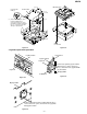
REMOVING AND REINSTALLING THE MAIN PARTS
MD MECHANISM SECTION
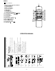
Perform steps 1 to 3 of the disassembly method to remove the
MD mechanism.
How to remove the magnetic head
(See Fig. 10-1)
1. Remove the screws (A1) x 1 pc.
Caution:
Take utmost care so that the magnetic head is not damaged
when it is mounted.
How to remove the cartridge holder
(See Fig. 10-2)
1. Open the rpller arm lever in the arrow direction, and lower
the clamper lever to the rear side.
2. Apply +5V to the red line side of blue connector of loading
motor, push the rack gear in the arrow direction to move the
cam plate lever until tick is heard.
3. Remove the screw (B1) x1 pc., and the spring (B2) x1 pc.,
fitted to the holder arm, and shift the cartridge holder to the
left side to remove it.
How to remove the mechanism switch PWB
(See Fig. 10-3)
1. Remove the screws (C1) x 2 pcs., and remove the mecha-
nism switch PWB.
Figure 10-1
Figure 10-2
Figure 10-3
MD Mechanism
(A1)x1
ø1.7x5mm
Magnetic Head
Slider Lever
Cartridge Holder
Clampa Lever
Lack Gear
Roller Arm Lever
Loading Motor
Cam Plate Lever
(B1) x1
ø1.7x5mm
(B2) x1
(C1)x1
ø1.7x3mm
(C1)x1
ø1.7x9.5mm
MD Mechanism
Switch PWB