
Service manual


– 15 –
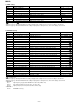
MD-R2
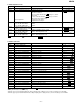
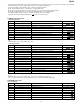
Step 1 Testmode STOP state [ t s m e ]
Step 2
Press the ENTER button three times.
RESULT sub-menu [ _ R S T _ Y O B I _ ]
Step 3 Press once the MD PLAY button. Indication of set value [ R F G : _ _ _ _ _ ]
Step 4 Press once the ENTER button. Indication of set value [ R C G : _ _ _ _ _ ]
Step 5 Press once the ENTER button. Indication of set value [ R T G : _ _ _ _ _ ]
Step 6 Press once the ENTER button. Indication of set value [ G T G : _ _ _ _ _ ]
Step 7 Press once the ENTER button. Indication of set value [ P C H : _ _ _ _ ]
Step 8 Press once the ENTER button. Indication of set value [ G C H : _ _ _ _ ]
Step 9 Press once the ENTER button. Indication of set value [ S A G : _ _ _ ]
Step 10 Press once the ENTER button. Indication of set value [ S B G : _ _ _ ]
Step 11 Press once the ENTER button. Indication of set value [ S E G : _ _ _ ]
Step 12 Press once the ENTER button. Indication of set value [ S F G : _ _ _ ]
Step 13 Press once the ENTER button. Indication of measurement value [ H A O : _ _ _]
Step 14 Press once the ENTER button. Indication of measurement value [ H B O : _ _ _]
Step 15 Press once the ENTER button. Indication of measurement value [ H E O : _ _ _]
Step 16 Press once the ENTER button. Indication of measurement value [ H F O : _ _ _]
Step 17 Press once the ENTER button. Indication of measurement value [ L A O : _ _ _]
Step 18 Press once the ENTER button. Indication of measurement value [ L B O : _ _ _]
Step 19 Press once the ENTER button. Indication of measurement value [ L E O : _ _ _]
Step 20 Press once the ENTER button. Indication of measurement value [ L F O : _ _ _]
Step 21 Press once the ENTER button. Indication of measurement value [ T C O : _ _ _ _]
Step 22 Press once the ENTER button. Indication of adjustment error sequence No. [ Y O B : _ _ _ _]
Step 23 Press once the ENTER button. Indication of adjustment status [ D I F : _ _ _ _]
Step 24 Press once the ENTER button. Indication of pre-adjustment not completed (00)/completed (4B) [ A D J : _ _ _ _]
Step 25 Press once the MD STOP button. RESULT sub-menu state [ _ R S T _ Y O B I _ ]
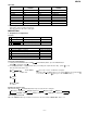
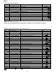
2. AUTO adjustment mode
Step No.
Setting Method
Remarks Display
Step 1 Testmode STOP state [ t s m e ]
Step 2
Press the ENTER button two times.
AUTO adjustment menu [ A U T O _ A J S T _ ]
Step 3 Press once the MD PLAY button. The slide moves to the innermost periphery, and automatic [ : _ _ _ _ _ _ ]
adjustment is started.
• In case of high reflection disc changes as follows.
PEG→HAG
•In case of low reflection disc changes as follows.
PEG→LAG→GCG→GEG→LAG
End of adjustment If adjustment is OK, Step 4.
If adjustment is NG, Step 7.
Step 4 Adjustment value output [ _ C O M P L E T E _ ]
Press the MD PLAY button. STEP 5
Press the MD STOP button. STEP 2
Step 5 Continuous playback (pit section) [ s c ]
Continuous playback (groove section)
[ a c ]
Step 6 Press the DISPLAY button. Continuous playback (groove section) [ a a ]
Press the MD STOP button. STEP 2 AUTO adjustment menu
Step 7 Adjustment value output [ C a n ' t _ A D J . ]
Press the MD STOP button. STEP 2 AUTO adjustment menu
• : Adjustment name, : Measurement value, : Address
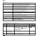
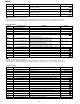
3. RESULT sub-mode
Step No.
Setting Method
Remarks Display
•
: Measurement value, : Adjustment value, : Other various informations
• ressing the REC button causes reversing.
• When the jog key is turned upward while the setting is displayed, the setting increases, and a new setting is stored in RAM.
• When the jog key is turned downward while the setting is displayed, the setting increases, and a new setting is stored in RAM.