
Service manual


MD-R2
– 2 –
General
Type: MiniDisc deck
Signle readout: Non-contact, 3-bean semi-conductor
laser pick-up
Audio channels: Stereo 2 channels/monaural
(long-play mode) 1 channel
Frequency response: 4 - 20,000 Hz (+0/-1 dB)
Rotation speed: Approximately 400 to 900 rpm
Error correction: ACIRC (Advanced Cross Interleave
Reed-Solomon Code)
Coding: ATRAC (Adaptive TRansform
Acoustic Coding)
Recording method: Magnetic modulation overwrite
method
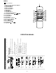
Input sockets
Timer/clock
Type: Digital clock with date function
Timer: ON/OFF, once a day
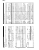
LINE IN Pin jack Over 680 mVrms 170 mVrms
22 kohms
OPTICAL Square
IN (Optical)
optical
connector
COAXIAL Pin jack 75 ohms 500 mVp-p
(Coaxial)
FOR A COMPLETE DESCRIPTION OF THE OPERATION OF THIS UNIT, PLEASE REFER
TO THE OPERATION MANUAL.
SPECIFICATIONS
A/D,D/A converter: 1-bit
Sampling frequency: 44.1kHz
Wow and flutter: Unmeasurable (less than ±0.001%
W.peek)
Signal/noise ratio: 100 dB or better during playback
(line output)
Power source: AC 120 V, 60 Hz
Power consumption: 17 W
Dimensions: Width: 16-15/16" (430 mm)
Height: 3-11/16" (93 mm)
Depth: 11-15/16" (302 mm)
Weight: 8.0 Ibs (3.6 kg)
Output sockets
Remote control
Power: DC 3V ("AA" (UM/SUM-3, R6, HP-7
or similar) battery included x 2)
Specifications for this model are subject to change without
prior notice.
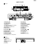
IMPORTANT SERVICE NOTES
Socket
name
Socket
shape
Input
impedance
Reference
input level
Minimum
input level
Socket
name
Output
level
Load
impedance
PHONES 1/4" (6.3 mm) stereo 15 mV 32 ohms
(Headphones)
jack
LINE OUT Pin jack 2 Vrms 50 kohms
OPTICAL
Square optical connector
OUT (Optical)
Socket shape
BEFORE RETURNING THE AUDIO PRODUCT
(Fire & Shock Hazard)
Before returning the audio product to the user, perform the following
safety checks.
1. Inspect all lead dress to make certain that leads are not pinched or
that hardware is not lodged between the chassis and other metal
parts in the audio product.
2. Inspect all protective devices such as insulating materials, cabinet,
terminal board, adjustment and compartment covers or shields,
mechanical insulators etc.
3. To be sure that no shock hazard exists, check for leakage current
in the following manner.
* Plug the AC line cord directly into a 120 volt AC outlet.
* Using two clip leads, connect a 1.5k ohm, 10 watt resistor paralleled
by a 0.15µF capacitor in series with all exposed metal cabinet parts
and a known earth ground, such as conduit or electrical ground
connected to earth ground.
* Use a VTVM or VOM with 1000 ohm per volt, or higher, sensitivity
to measure the AC voltage drop across the resistor (See diagram).
* Connect the resistor connection to all exposed metal parts having a
return path to the chassis (antenna, metal cabinet, screw heads,
knobs and control shafts, escutcheon, etc.) and measure the AC
voltage drop across the resistor.
All check must be repeated with the AC line cord plug connection
reversed.
Any reading of 0.3 volt RMS (this corresponds to 0.2 milliamp. AC.)
or more is excessive and indicates a potential shock hazard which
must be corrected before returning the audio product to the owner.
TO EXPOSED
METAL PARTS
CONNECT TO
KNOWN EARTH
GROUND
TEST PROBE
0.15 µ F
1.5k ohms
10W
VTVM
AC SCALE